Device and method for spinal surgery

a spinal surgery and device technology, applied in the field of spinal surgery devices and methods, can solve the problems of high risk of interpatient contamination, high risk of decontamination and sterilisation, and almost impossible to perform correctly

Active Publication Date: 2013-01-17
SAFE ORTHOPAEDICS SAS
View PDF49 Cites 15 Cited by
  • Summary
  • Abstract
  • Description
  • Claims
  • Application Information

AI Technical Summary

Benefits of technology

[0025]According to one embodiment, the distal end of the mounting tube comprises an indentation for positioning a handle-type perpendicular retaining element. This perpendicular retaining element is mainly used during tightening of the locking element with a counter-torque effect, thereby avoiding rotation of the assembly of the bone anchoring element and the mounting tube.
[0086]According to one embodiment, the straight handle may also allow gripping the locking element and guiding the latter on the bone anchoring element. This grip is arranged in order to securely retain the locking element in its end near the shape complementary with the head of the bone anchoring implant.

Problems solved by technology

The risk of interpatient contamination is very high; cleaning, decontamination and sterilisation are steps which are sometimes almost impossible to perform correctly in view of complex designs with many cavities inside the instruments.
These steps are a financial burden for the hospitals and represent very high costs, both in human and material terms.
Loss, breakage, wear and damage of an instrument may result in disastrous consequences for the patient or even cause cancellation of the surgery.
The logistics also present many disadvantages; cumbersome and costly both for the industrialist and the hospital, they most often involve significant inventories.
The rotations of sets between the hospital and the industrialist's logistics service are therefore very large in number, which significantly increases the risks of losses and errors.
Apart from the disadvantage of only offering a single screw length and diameter for the bone anchoring, this method only describes a single type of instrument: a screwdriver shank and its handle.
This international application does not offer any technical solution for designing and manufacturing instruments subject to major stresses such as the vertebral distractor which is absolutely essential for inserting the implant.

Method used


Image

  • Device and method for spinal surgery
  • Device and method for spinal surgery
  • Device and method for spinal surgery

Examples


Embodiment Construction

)

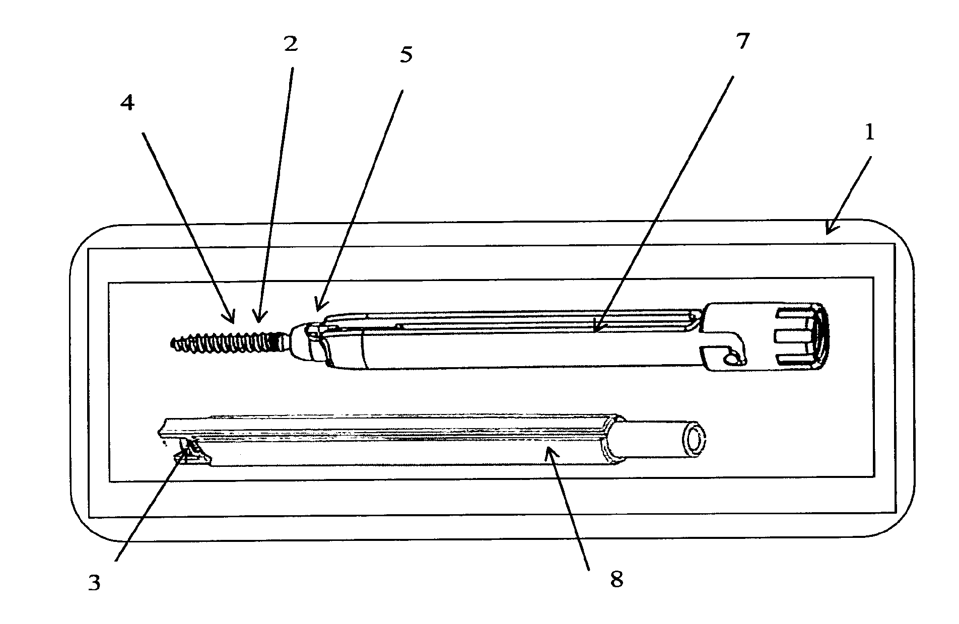
[0124]With reference to FIG. 1, a device (1) designed to be fixed on to a vertebra is described, comprising a means of bone anchoring (2) and its means of closure (3), respectively interdependently pre-mounted on tubes (7) and (8), all prepared at the factory in disposable sterile sealed packaging.

[0125]In order to facilitate reading of that which follows, the device 1 described above will subsequently be referred to as “screw device (1)”.

[0126]In a specific configuration not illustrated, the screw device (1) may comprise several means of bone anchoring (2) and several means of closure (3) interdependently pre-mounted on disposable tubes (7) and (8), all in a same disposable sterile sealed packaging.

[0127]The means of bone anchoring (2) consists of a threaded portion (4) designed to be inserted into the bone and a head portion (5) intended to receive a rod-type or plate-type connecting element (6).

[0128]In order to facilitate reading of that which follows, the bone anchoring elemen...


PUM


Abstract

Instrumentation for fixing at least two spinal vertebrae by pedicle screw type bone anchoring implants and connecting elements via the posterior or posterolateral approach has at least one bone anchoring element designed to be fixed to a vertebra, pre-mounted with a disposable mounting tube and a sterile sealed packaging. A kit of instruments for inserting or removing a spinal implant, has at least two threaded bone anchoring elements, a rod-type or plate-type connecting element mechanically connecting the bone anchoring elements and locking elements for locking the connecting element in position in relation to the anchoring elements, in order to perform all of the surgical procedures relating to the insertion or removal of the implant, all of the required instruments are disposable and packed in a sterile manner in one or several sealed packagings.

Description

CROSS REFERENCE TO RELATED APPLICATIONS[0001]The instant application is a divisional application of U.S. patent Ser. No. 13 / 518,949, filed Jun. 25, 2012, entitled DEVICE AND METHOD FOR SPINAL SURGERY (Our Ref: 12-228).BACKGROUND[0002]The invention relates to a device allowing performance of spinal stabilisation by a screw-type bone anchoring element via the posterior or posterolateral approaches.[0003]The device according to the invention is designed particularly, but not exclusively, for lumbar, thoracic or furthermore posterior cervical spinal osteosynthesis via minimally invasive or open surgical approaches.[0004]In the conventional method in itself, in case of anatomical dysfunctions of the vertebral column, pedicle screw-type bone anchoring elements are inserted (installed) in the vertebrae, interconnected by rod-type or plate-type connecting elements.[0005]The state of the art in the field of vertebral column surgery involves providing hospitals with implants and sets of instr...

Claims


Application Information

Patent Timeline
Patent Type & Authority Applications(United States)
IPC IPC(8): A61B17/70
CPCA61B17/7076A61B17/7079A61B2019/0278A61B19/026A61B19/0271A61B17/7085A61B50/30A61B50/33A61B2050/3008A61B2090/037A61B17/7082A61B17/7091A61B17/8875
Inventor PETIT, DOMINIQUE
Owner SAFE ORTHOPAEDICS SAS
Why Eureka
Try Eureka