
Method and device for the gravimetric and in-series distribution of solution

a gravimetric and in-series technology, applied in the direction of liquid bottling, packaging under special atmospheric conditions, weighing apparatus, etc., can solve the problems of reducing the service life of this means, slowing down the distribution further, and significant time loss, so as to increase the speed of the distribution of solutions, improve the continuity of delivery of solutions, and pour into containers more smoothly

Inactive Publication Date: 2013-01-24
INTERLAB
View PDF10 Cites 8 Cited by
  • Summary
  • Abstract
  • Description
  • Claims
  • Application Information

AI Technical Summary

Benefits of technology

The invention proposes a device and method for distributing solution in a way that requires less energy. The device can use multiple peristaltic pumps that work out of phase, which helps to ensure that the solution is delivered smoothly. This patent aims to provide a more efficient and effective way of distributing solutions.

Problems solved by technology

This slows down the distribution still further.
Such slowing down is particularly detrimental and causes a significant loss of time in the case of in-series distribution.
Moreover, the fact of modifying the operation of the delivery means reduces the service life of this means.

Method used


Image

  • Method and device for the gravimetric and in-series distribution of solution
  • Method and device for the gravimetric and in-series distribution of solution
  • Method and device for the gravimetric and in-series distribution of solution

Examples


first embodiment

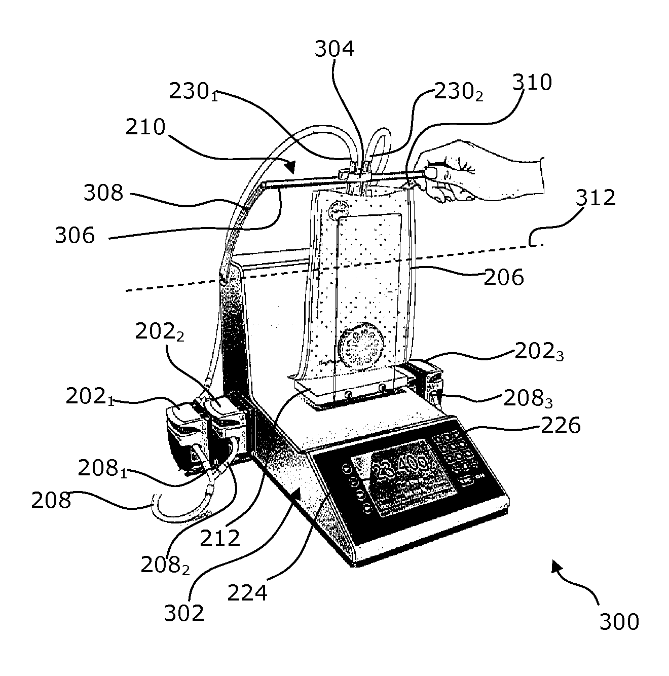
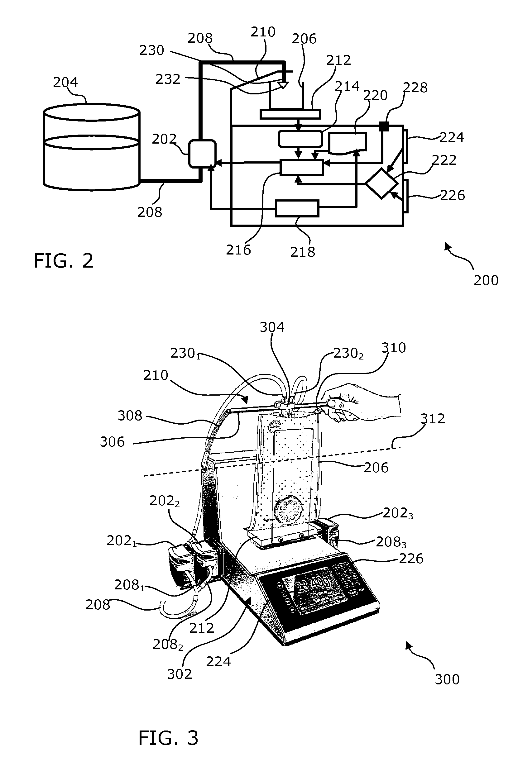
[0047]FIG. 2 is an exploded diagrammatic representation of a device 200 according to the invention. The device 200 comprises at least one non-contact delivery means 202 carrying out the delivery of a solution from a reservoir 204 as far as a container 206 through a delivery tube 208. The delivery means 202 can comprise one or more peristaltic pumps.

[0048]One of the ends of the delivery tube 208 is connected to the reservoir 204, and the other end is arranged on a support 210 that positions it over the container 206.

[0049]The device 200 has scales 212 on which the container 206 is arranged, and a module 214 is connected to the scales 212 and receives from the scales 212 a weight value corresponding to the weight of the solution present in the container 206. The module 214 is moreover arranged to compare the measured weight value with a desired weight value corresponding to a predetermined quantity of solution to be delivered into the container 206.

[0050]The module 214 is connected to...

second embodiment

[0061]FIG. 4 is a diagrammatic representation of a device 400 according to the invention. The device 400 shown in FIG. 4 comprises all the components of the device 200 of FIG. 2. In the device 400, the support 210 is mounted mobile in the three spatial directions. The device 400 also has motorization means 402 that can be actuated. The motorization means 402 can comprise one or more motors, for example stepper motors and one or more belts or slides that can move a holding element for the pouring end in two or three spatial dimensions to position it over a particular container in turn. The motorization means 402 are connected to the actuation module 216, which actuates these means 402 as a function of data received by the planning module 222.

[0062]FIG. 5 is a diagrammatic representation of a second example of a device 500 according to the invention carrying forth the embodiment of FIG. 4. The device 500 shown in FIG. 5 is presented in the form of a unitary piece assembly with a body ...


PUM

PropertyMeasurementUnit
weightaaaaaaaaaa
pressureaaaaaaaaaa
timeaaaaaaaaaa

Abstract

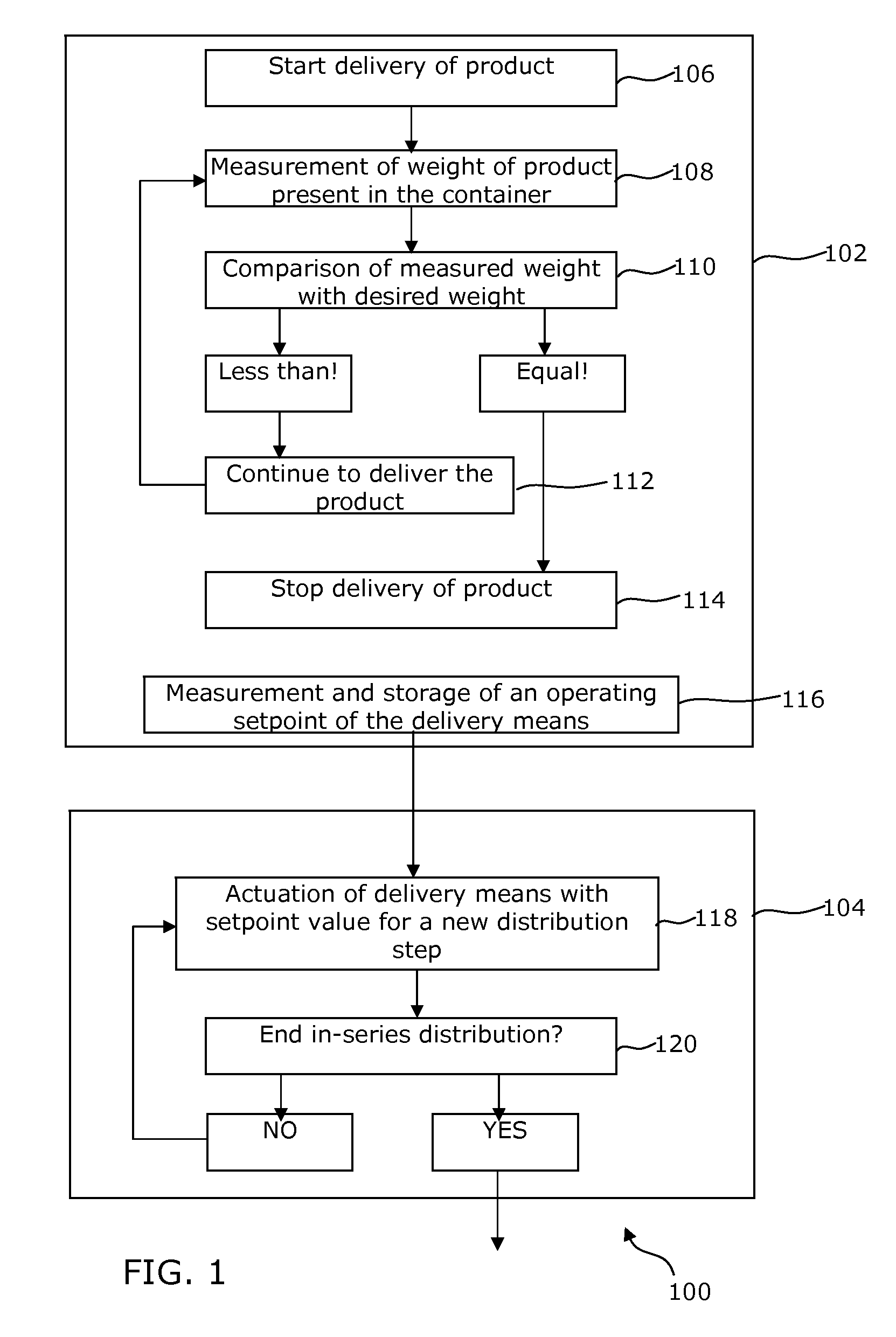
A method and device for the gravimetric and in-series distribution of a predetermined quantity of a solution. The device has a delivery mechanism for delivering a solution, a weighing mechanism and a mechanism for measuring an operating value to establish a setpoint value of the delivery mechanism during a calibration step during which the weighing mechanism is used for the delivery of a predetermined quantity of solution. The device also has an actuating mechanism to actuate the delivery mechanism with the setpoint value to carry out one or more distribution steps with the delivery of the predetermined quantity of solution without using the weighing mechanism.

Description

FIELD OF THE INVENTION[0001]The invention disclosed herein is in the field of the in-series distribution of liquid or viscous solution, particularly in the field of dilution. Embodiments of the invention relate more particularly to the field gravimetric in-series distribution of solution and still more particularly to a method and a device for the gravimetric in-series distribution of a given quantity of liquid solution with gravimetric distribution being understood to mean a distribution of solution into a container to which the solution is conveyed by one or more delivery means to a point situated above the container at a non-zero distance from the bottom of the container or from a filling opening of the container, the solution then flowing into the container by gravity.BACKGROUND OF THE INVENTION[0002]Several devices for the gravimetric distribution of a predetermined quantity of a solution are currently known. In most of these devices, the distribution is carried out with the so...

Claims


Application Information

Patent Timeline
Patent Type & Authority Applications(United States)
IPC IPC(8): B65B1/30
CPCG01G17/06B01L3/0293G01N35/1016G01F25/14
Inventor JALENQUES, M. EMMANUEL
Owner INTERLAB
Learn More