
Depth-of-Interaction in an Imaging Device

a technology of depth-of-interaction and imaging device, which is applied in the field of imaging system, can solve the problems of introducing degradations in other pet system performance criteria, such as sensitivity, energy resolution and, often, timing

Active Publication Date: 2013-01-24
SIEMENS MEDICAL SOLUTIONS USA INC
View PDF1 Cites 15 Cited by
  • Summary
  • Abstract
  • Description
  • Claims
  • Application Information

AI Technical Summary

Benefits of technology

The present invention provides a method for determining the position of annihilation photons in a PET scanner by capturing the photons and converting them into optical photons. The optical photons are then collected by a photosensor and the arrival time of each photon is recorded. By analyzing the differences in the optical photon path lengths and the arrival times, the depth of interaction of the annihilation photons can be determined. This information can be used to improve the accuracy of PET scanners and to localize temporal photon pairs. The invention also provides a PET scanner comprising a scintillator, a photosensor, and a data processor for analyzing the optical photon path lengths and arrival times.

Problems solved by technology

However, these proposed methods suffer from complexity and cost, and introduce degradations in other PET system performance criteria, such as sensitivity, energy resolution and, often, timing.

Method used


Image

  • Depth-of-Interaction in an Imaging Device
  • Depth-of-Interaction in an Imaging Device
  • Depth-of-Interaction in an Imaging Device

Examples


Embodiment Construction

[0029]FIG. 3 is an illustration of a scintillator 60 for a PET system to show the operation of a method carried out according to an embodiment of the present invention. The scintillator 60 may be formed from any appropriate scintillation crystal, such as LSO, LYSO, BGO, etc. The scintillator 60 has a length L, a width W, an index of refraction n (not shown), and three representative depths of interaction (DOIs): U1 near the top, U2 at the center and U3 at the bottom, or exit, of the scintillator 60. Typical values for an LSO-based scintillator 60 of some of these parameters may be L=20 mm, W=4 mm, n=1.82. The speed of light c in a vacuum is 0.30 mm / ps, so the ratio of the index of refraction to the speed of light (n / c) is 6.07 ps / mm.

[0030]The shortest distance between an actual DOI and the top of the scintillator 60 from which the light must reflect to be detected is represented by a double-headed arrow LR. The shortest distance between the actual DOI and the exit to the photosensor...


PUM


Abstract

A method (70) of operation of a PET scanner (10) that determines the depth of interaction of the annihilation photons within the scintillator (32) in localizing a temporal photon pair along a line of response (LOR).

Description

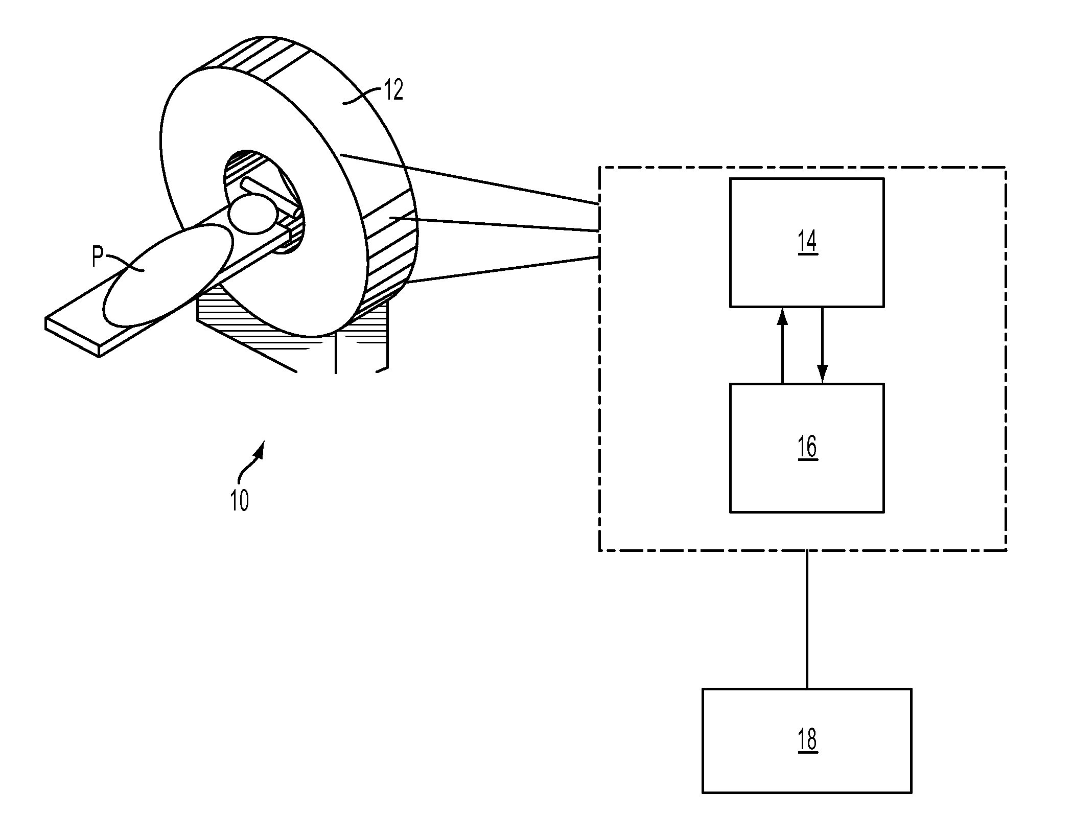
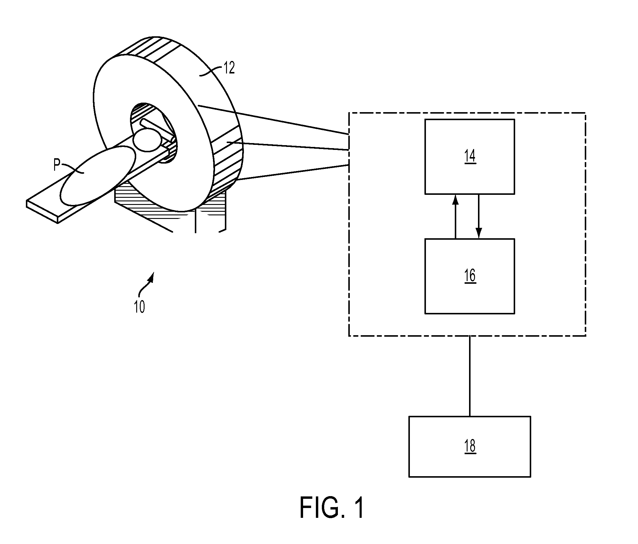
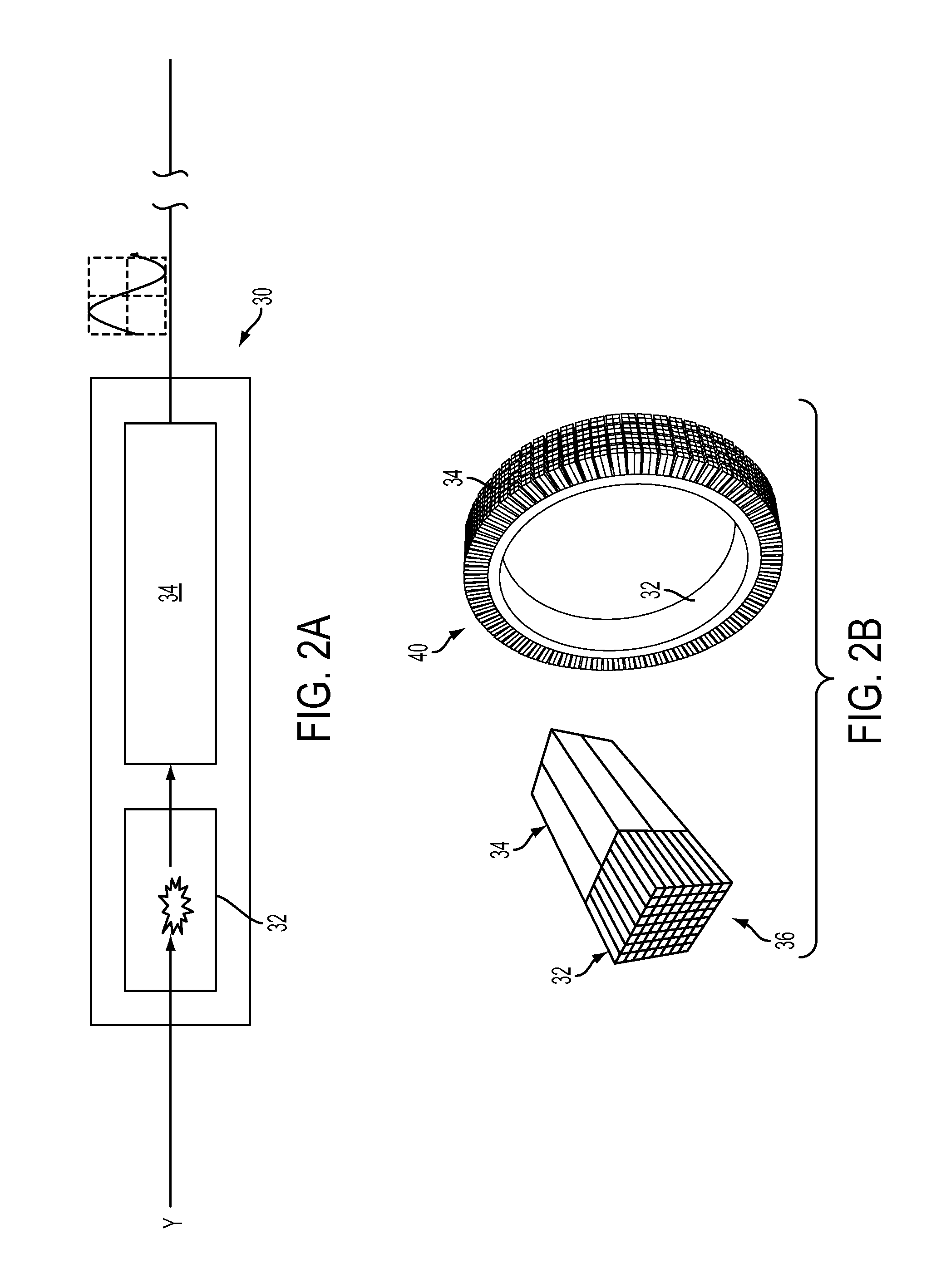
CROSS-REFERENCE TO RELATED APPLICATIONS[0001]This application claims the benefit of U.S. Provisional Patent Application 61 / 509,606, filed on Jul. 20, 2011, the entire disclosure of which is hereby incorporated by reference.FIELD OF THE INVENTION[0002]This invention generally relates to imaging systems and, more particularly to, positron emission tomography (PET) scanners.BACKGROUND OF THE INVENTION[0003]Positron emission tomography (PET), also known as PET imaging, is a type of nuclear medicine imaging that uses radioactive material, placed in a patient's body, to identify molecular activity and processes and, thus, assist in diagnosing disease, evaluating medical conditions, monitoring a patient's response to therapeutic interventions, etc. As shown in FIG. 1, a PET system 10 generally comprises an imaging device 12 that can detect radioactive emissions from the radioactive material (also known as radiopharmaceuticals or radiotracers) in the internal body area P under examination, ...

Claims


Application Information

Patent Timeline
Patent Type & Authority Applications(United States)
IPC IPC(8): G01T1/164
CPCA61B6/037G01T1/2985
Inventor SIEGEL, STEFAN B.MINTZER, ROBERT A.
Owner SIEMENS MEDICAL SOLUTIONS USA INC
Learn More