Electrical Machines

a technology of electrical machines and rotors, which is applied in the direction of mechanical energy handling, dynamo-electric machines, supports/enclosements/casings, etc., can solve the problems of difficult to ensure, difficult to manufacture and assembly of rotating electrical machines with internal and external cylindrical stators, and complex construction of rotors for low speed high-torque rotating electrical machines, etc., to achieve the effect of facilitating manufacturing and assembly, facilitating operation and facilitating operation

Active Publication Date: 2013-01-24
GE ENERGY POWER CONVERSION TECH
View PDF11 Cites 16 Cited by
  • Summary
  • Abstract
  • Description
  • Claims
  • Application Information

AI Technical Summary

Benefits of technology

[0015]By mounting magnets with appropriate magnetic strengths on the first and second support surfaces of each rotor element, it is possible to reduce the net magnetic force acting on each rotor element and, hence, on the guide arrangement. This may reduce the complexity of the components used in the manufacture and assembly of the electrical machine and thereby reduce its cost. In particular, the net magnetic force acting on the rolling elements may be reduced. This may enable the use of smaller diameter, and hence higher speed, rolling elements, resulting in reduced component complexity and cost. It would typically be necessary to ensure that the net magnetic force acts to maintain the rolling elements in contact with the guide arrangement.
[0019]The first and second rotor sections may be movable relative to each other in a direction generally perpendicular to the operational direction of movement of the rotor (i.e. perpendicular to the direction of movement of the rotor during normal operation of the electrical machine). The first and second rotor sections may be resiliently biased apart to maintain contact respectively with the first and second guide arrangements. Manufacture and assembly of the electrical machine is thereby further simplified as the first and second rotor sections are independently guided along the first and second guide arrangements and are thus able to independently follow the geometry of the first and second stators. The electrical machine can, therefore, operate effectively even if there is misalignment between the first and second stators.
[0020]When the electrical machine is a rotating electrical machine, the first and second rotor sections may be movable relative to each other in a radial direction and / or in an axial direction. The first and second rotor sections may be resiliently biased apart in the radial direction to maintain contact respectively with the first and second guide arrangements. The ability of the first and second rotor sections to move relative to each other, and in particular to move relative to each other in the radial direction in the case of a rotating electrical machine, ensures that the first and second rotor sections can independently follow the geometry of the first and second guide arrangements and, hence, independently follow the geometry of the first and second stators. Accordingly, it is not necessary for the first and second stators to be fully concentric. When the electrical machine is a rotating electrical machine, the ability of the first and second rotor sections to move relative to each other in the axial direction further ensures that the electrical machine can operate effectively even if there is axial misalignment of the first and second guide arrangements and / or the first and second stators.
[0022]One or both of the first stator and the second stator may be formed by a plurality of stator segments. This form of stator construction may further facilitate the manufacture and assembly of the electrical machine by making alignment of the first and second stators more straightforward.

Problems solved by technology

The construction of rotors for low speed high torque rotating electrical machines can be problematic, and this is especially the case for rotating electrical machines that have internal and external cylindrical stators.
It can be difficult to ensure concentricity and axial alignment of the cylindrical rotor and adjacent cylindrical stators and the manufacture and assembly of rotating electrical machines having internal and external cylindrical stators can thus be complex.

Method used


Image

  • Electrical Machines
  • Electrical Machines
  • Electrical Machines

Examples


Embodiment Construction

[0051]Embodiments of the present invention will now be described by way of example only and with reference to the accompanying drawings.

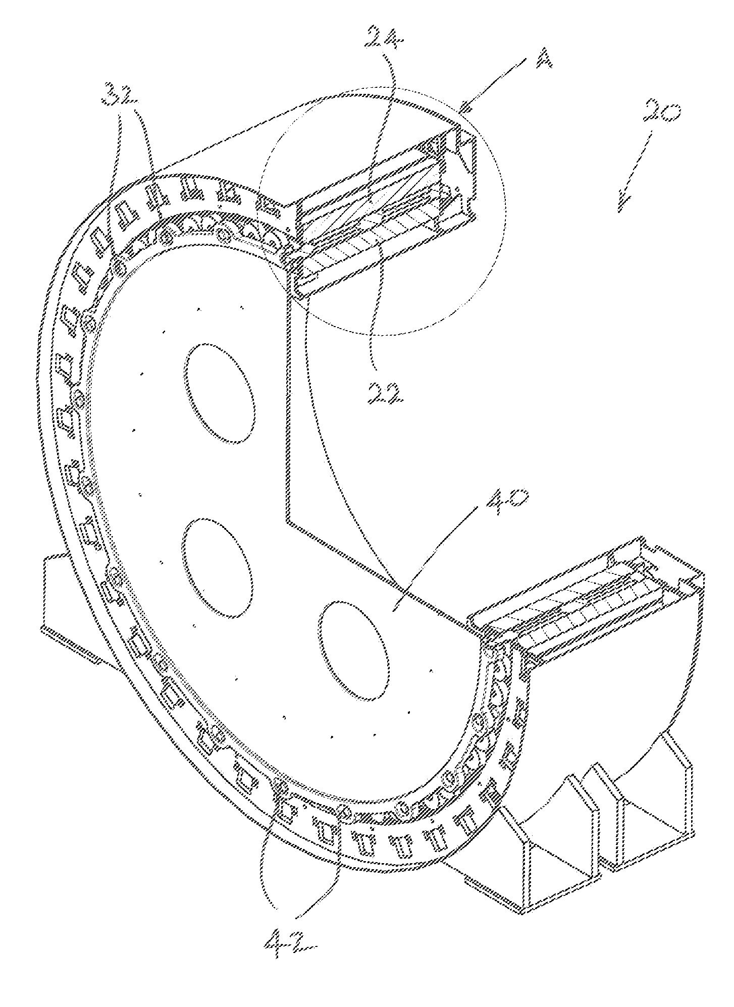
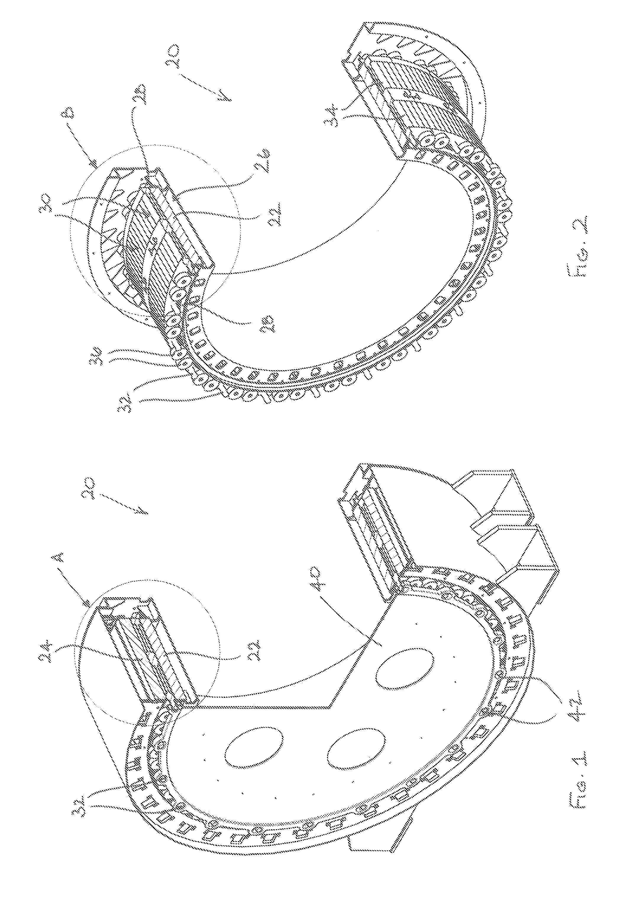
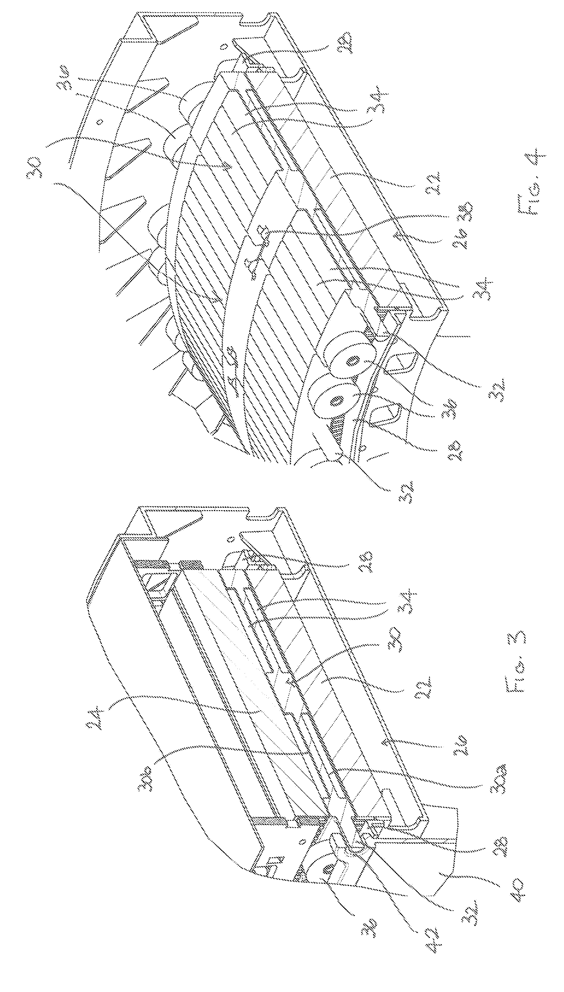
[0052]Referring initially to FIGS. 1 to 9, a radial flux rotating electrical machine 20 comprises a radially inner first cylindrical stator 22 and a radially outer second cylindrical stator 24 which is positioned radially outwardly of the first cylindrical stator 22. The first and second cylindrical stators 22, 24 are substantially concentric.

[0053]The first cylindrical stator 22 includes a circumferentially extending guide arrangement 26 which includes two axially spaced circumferential guide rails 28 (best seen in FIGS. 2 and 4). The rotating electrical machine 20 also includes a plurality of circumferentially arranged rotor elements 30 which cooperate with the guide rails 28 for rotation relative to the first and second cylindrical stators 22, 24. The rotor elements 30 cooperate with each other in the circumferential direction to form a continuou...


PUM


Abstract

An electrical machine 20, 48 comprises a first stator 22 and a second stator 24 spaced from the first stator 22, at least one of the first stator 22 and the second stator 24 including a guide arrangement 26, 50. The electrical machine 20, 48 also includes a plurality of rotor elements 30, 46 located between the first stator 22 and the second stator 24 and cooperating with the guide arrangement 26, 50 for movement relative to the first stator 22 and the second stator 24. Adjacent rotor elements 30, 46 cooperate with each other so that the rotor elements 30, 46 form a rotor and at least one of the rotor elements 30, 46 includes a coupling element 32 to transfer force to or from the rotor. Each rotor element 30, 46 includes a first support surface 30a which faces towards the first stator 22 and defines a first air gap with the first stator 22, a second support surface 30b which faces towards the second stator 24 and defines a second air gap with the second stator 24, and one or more magnets 34 mounted on each of the first and second support surfaces 30a, 30b in the first and second air gaps.

Description

FIELD OF THE INVENTION[0001]The present invention relates generally to electrical machines and more particularly to electrical machines having two stators. Embodiments of the present invention relate to a rotor construction for an electrical machine, and in particular but not exclusively to a rotor construction for a rotating electrical machine having internal and external substantially cylindrical stators.BACKGROUND TO THE INVENTION[0002]Rotating electrical machines typically comprise a cylindrical rotor mounted to rotate around or within an adjacent stator. A rotating electrical machine may thus have an internal substantially cylindrical rotor mounted within an external stator or an outer cylindrical rotor mounted around an internal stator. Some types of rotating electrical machine, such as a double output generator, have both internal and external substantially cylindrical stators with a rotor located between them.[0003]The construction of rotors for low speed high torque rotatin...

Claims


Application Information

Patent Timeline
Patent Type & Authority Applications(United States)
IPC IPC(8): H02K16/04
CPCH02K1/278H02K1/2786H02K41/03H02K16/04H02K21/12H02K16/00H02K1/279
Inventor BRADLEY, STUART IANALABASTER, DAVID
Owner GE ENERGY POWER CONVERSION TECH
Why Eureka
Try Eureka