
Liquid crystal display device

Inactive Publication Date: 2013-01-24
SHARP KK
View PDF2 Cites 7 Cited by
  • Summary
  • Abstract
  • Description
  • Claims
  • Application Information

AI Technical Summary

Benefits of technology

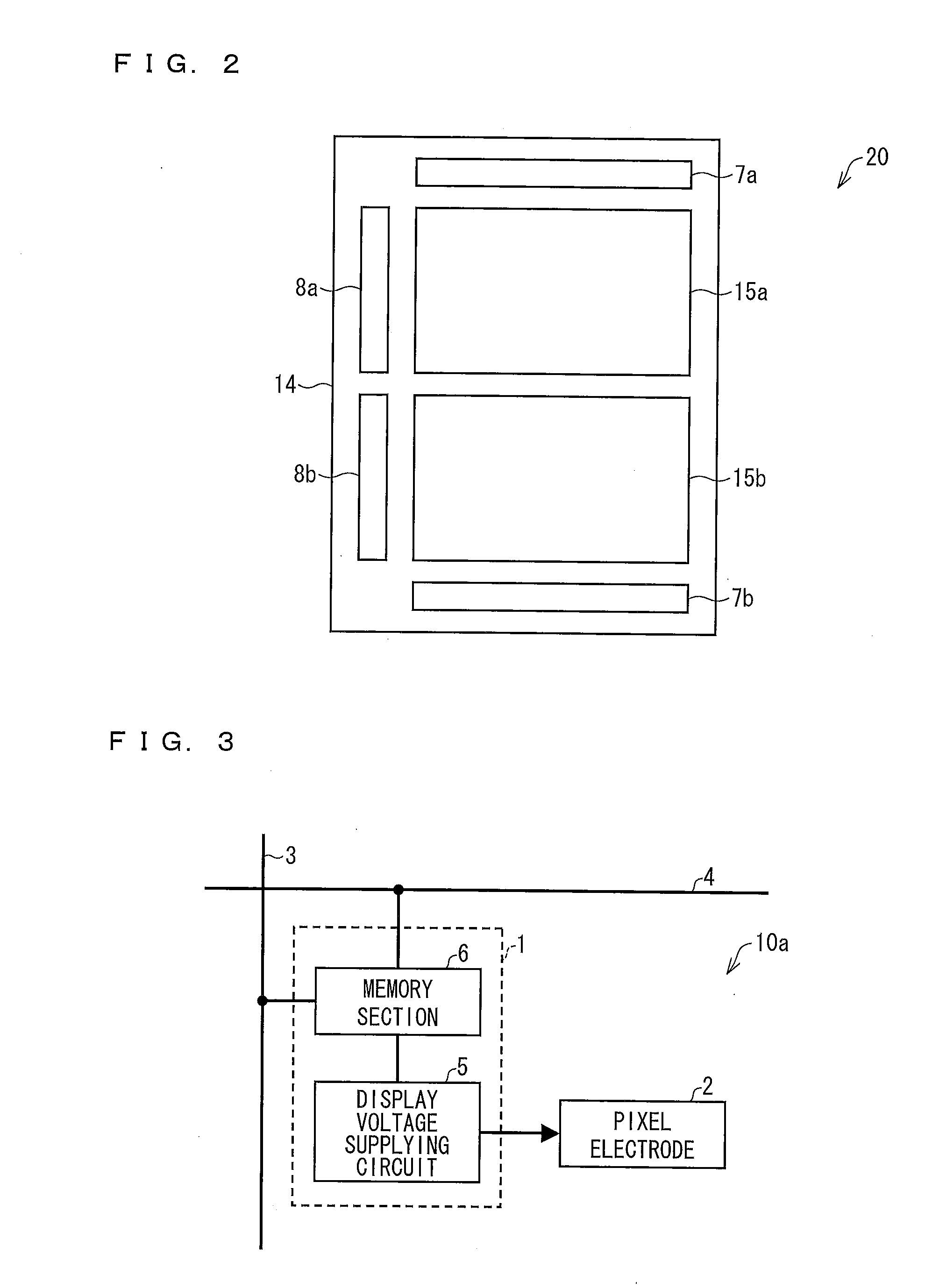
The present invention allows for displaying images without needing to continuously supply image data from the outside. Instead, the image data is stored in a memory circuit and then written onto a pixel electrode. This means that the image can be displayed without needing to run scanning and signal lines. This approach results in lower electric power consumption and improved image quality.

Problems solved by technology

However, since the backlight of the transmissive liquid crystal display device needs to be always in an on-state, the transmissive liquid crystal display device has a large electric power consumption.
However, since the reflective liquid crystal display device as described above has no backlight, an image displayed by the reflective liquid crystal display is hardly visible in a case where there is little light around the reflective liquid crystal display.
That is, the reflective liquid crystal display device is given limitations in terms of an environment in which the reflective liquid crystal display device is used.
In terms of low electric power consumption, reduction in electric power consumption of a display panel is an important issue.

Method used


Image

  • Liquid crystal display device
  • Liquid crystal display device
  • Liquid crystal display device

Examples


Embodiment Construction

[0027](Outline of Liquid Crystal Display Device 20)

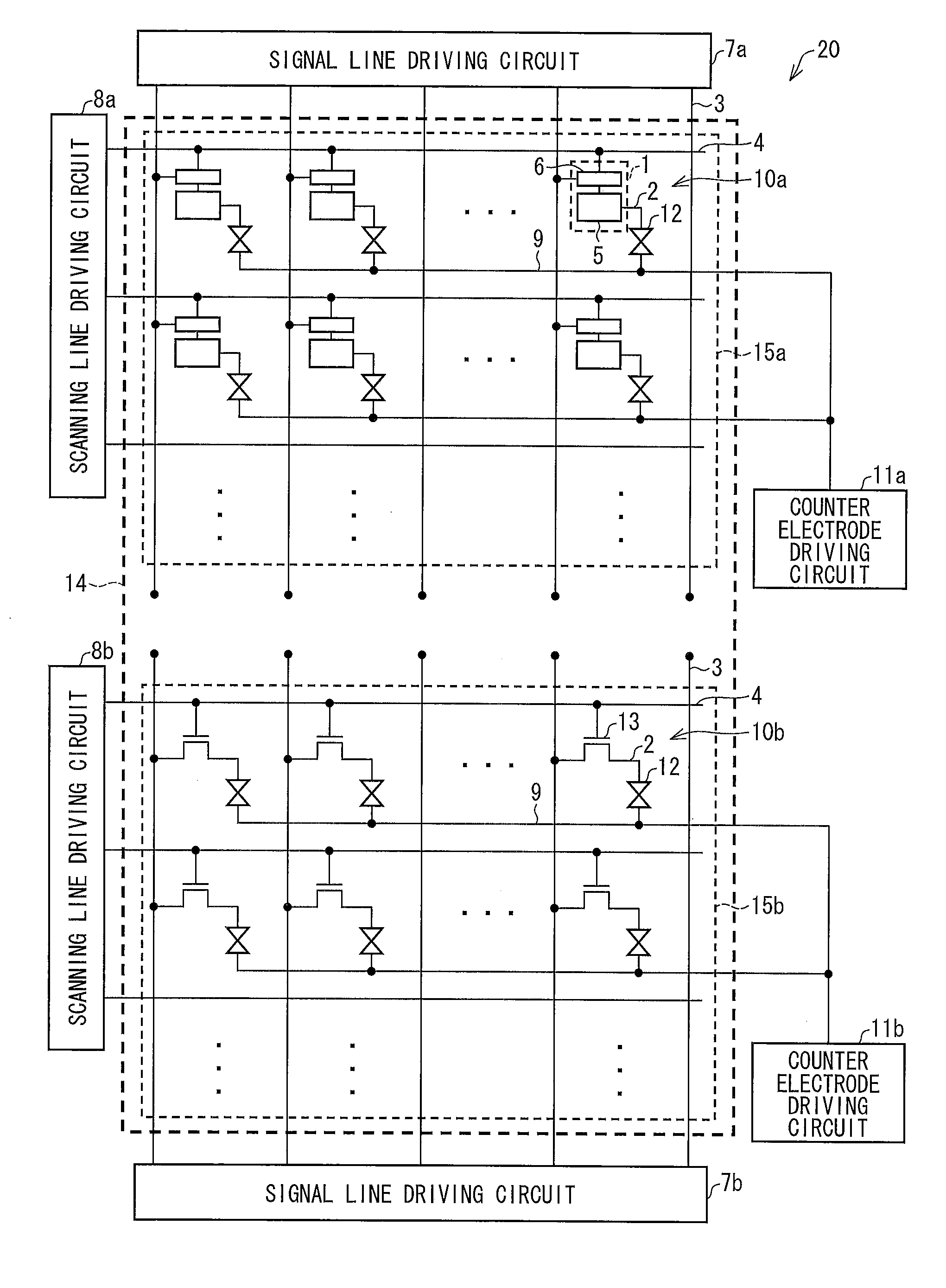
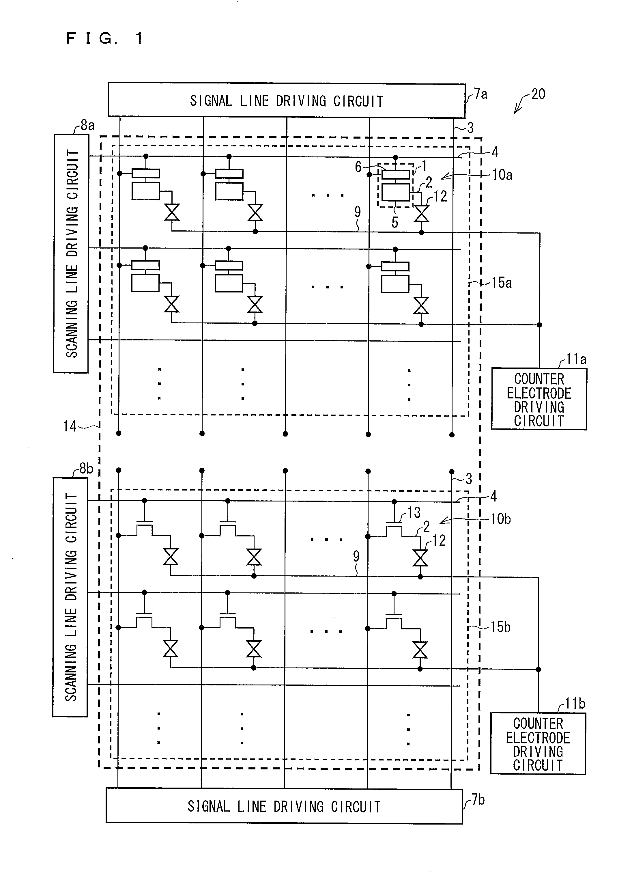
[0028]The following description will discuss an embodiment of the present invention with reference to drawings. First, an outline of a liquid crystal display device (LCD) in accordance with the present embodiment is discussed with reference to FIGS. 1 and 2. FIG. 1 is an equivalent circuit diagram illustrating an entire electric configuration of an LCD 20. FIG. 2 is a plan view schematically illustrating an entire configuration of the LCD 20.

[0029]As illustrated in FIG. 2, the LCD 20 includes a liquid crystal panel 14 (display screen), signal line driving circuits 7a and 7b, and scanning line driving circuits 8a and 8b. The liquid crystal panel 14 is divided into a display region 15a (first display region) and a display region 15b (second display region), both of which will be described later. In the display region 15a, an image is displayed in accordance with a reflective method or a transflective method. In the display region 15b,...


PUM


Abstract

In a liquid crystal display device (20), a liquid crystal panel (14) is divided into a display region (15a) including a plurality of pixels (10a) and a display region (15b) including a plurality of pixels (10b). A memory circuit (1) is provided to each pixel (10a) included in the display region (15a). The memory circuit (1) is capable of storing a data signal supplied from a signal line (3). As such, writing the data signal, which has been stored in the memory circuit (1), into a pixel electrode (2) allows an image to be displayed in accordance with the data signal. That is, in the display region (15a), it is possible to display an image without supplying image data from the outside via a scanning line (4) and the signal line (3). This allows a reduction in electric power consumption.

Description

TECHNICAL FIELD[0001]The present invention relates to a liquid crystal display device including a switching element for each pixel.BACKGROUND ART[0002]In recent years, research and development of display devices has been actively conducted, and a thin flat panel display (FPD) has come into wide use in place of a display device employing a cathode-ray tube, which was conventionally the mainstream. Examples of a display element used in the FPD include a liquid crystal, a light-emitting diode (LED), an organic electroluminescent (EL), or the like. Among many display mediums, a liquid crystal display device (LCD) employing a liquid crystal has been particularly actively researched and developed.[0003]Conventionally, the mainstream of liquid crystal display devices has been a transmissive liquid crystal display device in which a backlight provided on a rear surface of a display panel is turned on so as to display an image in a transmissive manner. However, since the backlight of the tran...

Claims


Application Information

Patent Timeline
IPC IPC(8): G09G3/36
CPCG09G3/3666G09G2300/0426G09G2300/0456G09G2300/0842G02F2001/133391G09G2330/021G02F1/133555G02F1/136213G09G2300/0857G02F1/133391
Inventor KAWASHIMA, YUKIYOSHIDA, KEISUKEFUJIKAWA, YOHSUKETASAKA, YASUTOSHIMORIYA, YOSHIMIZU
Owner SHARP KK
Learn More