Tag Used for Monitoring the Tire Pressure

Inactive Publication Date: 2008-10-30
NXP BV
View PDF7 Cites 2 Cited by
  • Summary
  • Abstract
  • Description
  • Claims
  • Application Information

AI Technical Summary

Benefits of technology

[0016]The features according to the invention enable monitoring of physical variables to be performed with substantially lower electric power consumption or shorter measuring time than according to the prior art, and the invention is therefore excellently suited for use in monitoring systems in which little electrical supply energy is available. The invention is especially suitable for use in those monitoring systems in which a physical variable that changes slowly with time is to be permanently monitored, such as, for example, the tire pressure in a motor vehicle tire. Furthermore, in many known monitoring systems, such as, for example, tire pressure-monitoring systems, the physical variable is indeed measured at regular intervals, but what is really of interest after a first recording of a measured value is the change in this physical variable over time, and not its absolute value. Through the invention, the physical variable value to be measured is displaced into a working range lying around a selected working point, the working range amounting to only a fraction of the total measurement range. If therefore, for example, the working range amounts to one quarter of the total measurement range, then for the same accuracy of measurement the measuring time can shortened to up to a quarter of the original measuring time or a corresponding reduction in the electric power consumption can be achieved. The invention can be very easily integrated into contactless data carriers and thus offers wide-ranging opportunities for application.
[0026]The advantage obtained in accordance with the measures of claim 13 is that the data carrier does not require its own energy supply in the form of a battery or rechargeable battery, rather is supplied externally via the received electromagnetic field, so that it is maintenance-free and can be installed in a completely closed housing.

Problems solved by technology

The use of such measuring methods and measuring systems presents problems in monitoring applications where relatively little energy is available, yet accurate measurements of a specific physical variable are to be made at regular intervals, as, for example, in the case of tire-pressure monitoring systems on motor vehicles.

Method used


Image

  • Tag Used for Monitoring the Tire Pressure
  • Tag Used for Monitoring the Tire Pressure
  • Tag Used for Monitoring the Tire Pressure

Examples


first embodiment

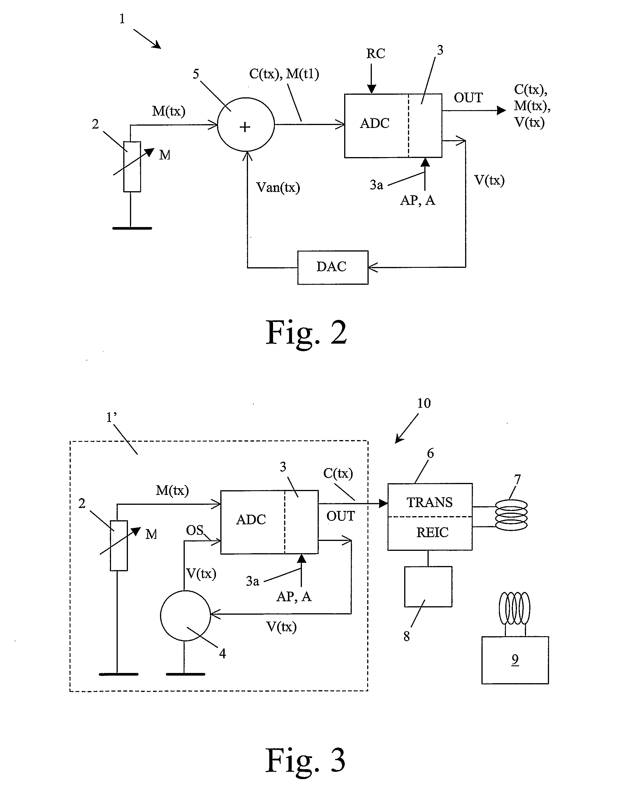
[0039]FIG. 2 illustrates a block diagram of a measuring system 1 according to the invention, which is designed to execute the measuring method according to the invention. The measuring system 1 comprises a sensor 2, which supplies analog measured values (M(tx) of the sensed physical variable M as its output signal. The measured values M(tx) emitted by the sensor 2 are supplied to an input of an analog digital converter ADC, which performs a digitization of the received signals and supplies the digitized values to calculation means 3, which are integrated in the analog-digital converter ADC. Furthermore, the measuring system according to the invention is provided with addition means, which comprise a summation circuit 5 connected between the sensor 2 and the analog-digital converter ADC as well as a digital-analog converter DAC. The measured values M(tx) of the sensor 2 are fed to one input of the summation circuit 5 and the output voltage Van(tx) supplied by the digital-analog conve...

second embodiment

[0042]A block diagram of a measuring system 1′ according to the invention that is integrated in a contactlessly readable data carrier 10 is shown in FIG. 3. The measuring system 1′ comprises a sensor 2, for example, a pressure or temperature sensor, which senses a physical variable M and sends measured values M(tx) to an analog digital converter ADC, which digitizes the received measured values and sends the digitized values to calculation means 3, which are integrated in the analog-digital converter ADC. The calculation means 3 have an input 3a for adjusting a working point AP and a working range A. From the received measured values M(tx) and the working point AP, the calculation means 3 calculate a displacement value V(tx) in accordance with the measuring method of the invention. This displacement value V(tx) is supplied to a controllable voltage source 4, which in response to the displacement value produces a d.c. voltage that is supplied to an offset voltage input OS of the anal...


PUM


Abstract

A measuring method for measuring physical variables comprises—the selection of a working point (AP) lying within a total measurement range (G) of a physical variable (M) to be measured,—the detection of a measured value (M(t1)) of the physical variable at a first measuring time (t1),—the determination of a displacement value (V(t1)) as the result of a subtraction of the measured value (M(t1)) measured at the first measuring time from the working point (AP),—the formation of change values (C(t2), C(t3) . . . C(tx)) of the physical variable (M) by acquiring subsequent measured values (M(t2), M(t3) . . . M(tx)) of the physical variable at subsequent measuring times (t2, t3 . . . tx) and addition of the displacement value (V(t1)) to the subsequent measured values.

Description

FIELD OF THE INVENTION[0001]The invention relates to a measuring method for measuring physical variables.[0002]The invention relates furthermore to a measuring system having a sensor for detecting a physical variable and for emitting measured values of the detected physical variable, and having an analog-digital converter for detecting the measured values emitted by the sensor.[0003]The invention relates furthermore to a data carrier.BACKGROUND OF THE INVENTION[0004]In the case of digital measuring methods and measuring systems, it is known that electric power consumption and the time required for measuring are dependent on the accuracy of the measurement, the product of electric power consumption and measuring time being relatively constant for a specific accuracy of measurement.[0005]The use of such measuring methods and measuring systems presents problems in monitoring applications where relatively little energy is available, yet accurate measurements of a specific physical varia...

Claims


Application Information

Patent Timeline
IPC IPC(8): B60C23/04
CPCB60C23/0408
Inventor SPIESS, BERNHARD GEORG
Owner NXP BV
Why Eureka
Try Eureka