Circuit and method for clock correction in telecommunication system

Inactive Publication Date: 2007-10-11
LAPIS SEMICON CO LTD
View PDF16 Cites 1 Cited by
  • Summary
  • Abstract
  • Description
  • Claims
  • Application Information

AI Technical Summary

Benefits of technology

[0006]In view of the foregoing, it is an object of the present invention to provide a low-cost circuit, mobile terminal, base station apparatus and method for correcting a clock and for appli

Problems solved by technology

Transceivers for use in radio communication systems have employed expensive reference clock generators which are configured to generate a reference clock having a center frequency in conformity with a standard specification without substantial temperature dependency corrections.
This digital modulator circuit, then, does not correct the h

Method used


Image

  • Circuit and method for clock correction in telecommunication system
  • Circuit and method for clock correction in telecommunication system
  • Circuit and method for clock correction in telecommunication system

Examples


first embodiment

1. First Embodiment

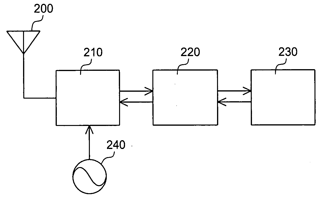
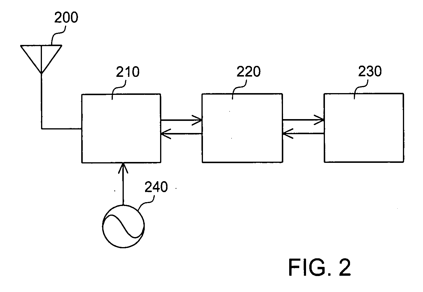
[0028]Each component and its operation in a communication apparatus of a first embodiment according to the present invention will de described with reference to the drawings. FIG. 2 is a block diagram showing a common configuration of the communication apparatus such as a base station, a fixed terminal or a mobile terminal which can be used in a radio communication system. The communication apparatus shown in FIG. 2 comprises an antenna 200, a transceiver circuit 210, a control circuit 220, a thermistor 230, and a reference clock generator 240.

[0029]The transceiver circuit 210 demodulates a reception signal and modulates a transmission signal. The control circuit 220 controls the transceiver circuit 210. The thermistor 230 measures an ambient temperature, and outputs the measurement result to the control circuit 220. The reference clock generator 240 supplies a clock signal required for operation of the transceiver circuit 210.

[0030]The transceiver circuit 210 wil...

second embodiment

2. Second Embodiment

[0046]In the following, a communication apparatus of a second embodiment according to the present invention will be described with reference to the drawings. In regard to the same configuration and operation as the communication apparatus of the first embodiment described above, a description thereon is omitted. FIG. 11 is a block diagram showing the configuration of an RF control circuit 10 of the second embodiment. The RF control circuit 1100 comprises a channel decoder 1110 for generating a frequency control value 1100a which is applied to a PLL circuit 422 of a synthesizer 420, and a transmission / reception switching circuit 510.

[0047]The channel decoder 110 comprises a reception frequency set value storage circuit 501, a transmission frequency set value storage circuit 502, a selector 503, and frequency correction circuits 1111, 1112. The frequency correction circuit 1111 adds or subtracts frequency correction information 216c to or from a frequency set value...


PUM


Abstract

Disclosed are a low-cost circuit, a communication apparatus and a method for correcting a clock and for application to a specific radio system with low electric power consumption. The communication apparatus comprises: a frequency data storage circuit for storing frequency set values corresponding to respective channels to output a frequency set value corresponding to a channel specified by a channel selection signal; a frequency correction circuit for calculating a frequency control value by performing a calculation using both the frequency control value and a frequency correction value determined in accordance with an ambient temperature; a voltage controlled oscillator for generating a first frequency based on a clock signal; and a PLL circuit for generating a desired second frequency by performing a calculation using the first frequency and the frequency control value.

Description

BACKGROUND OF THE INVENTION[0001]1. Field of the Invention[0002]The present invention relates to a telecommunication system, and more particularly, to clock correction technique for the telecommunication system.[0003]2. Description of the Related Art[0004]Transceivers for use in radio communication systems have employed expensive reference clock generators which are configured to generate a reference clock having a center frequency in conformity with a standard specification without substantial temperature dependency corrections. Patent Document 1 (Japanese Patent Application Kokai No. Hei5-102955) discloses a digital modulator circuit which eliminates the need for employing an expensive reference oscillator.[0005]The digital modulator circuit disclosed in Patent Document 1 has a memory circuit that stores frequency correction data, and controls a voltage-controlled oscillator to prevent changes in frequency with passage of time. This digital modulator circuit can be used for a comm...

Claims


Application Information

Patent Timeline
IPC IPC(8): H04B1/06
CPCH03L7/16H03L1/026
Inventor ICHIKAWA, TAKESHI
Owner LAPIS SEMICON CO LTD
Why Eureka
Try Eureka