Image pickup apparatus, solid-state image pickup element, and image pickup method
- Summary
- Abstract
- Description
- Claims
- Application Information
AI Technical Summary
Benefits of technology
Problems solved by technology
Method used
Image


Examples
first embodiment
1. First Embodiment
Functional Configuration Example of Image Pickup Apparatus
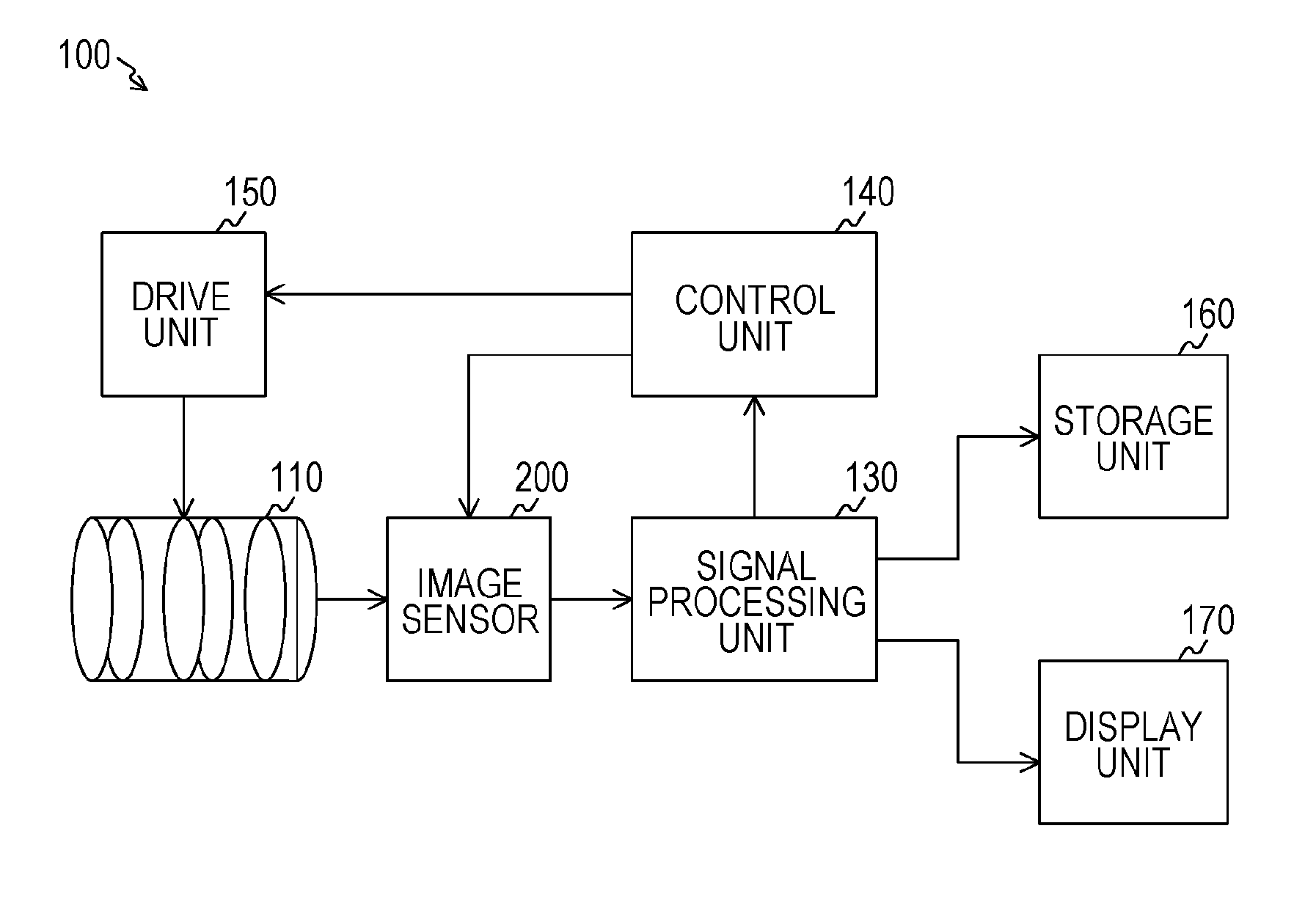
[0040]FIG. 1 is a block diagram illustrating a configuration example of an image pickup apparatus 100 according to a first embodiment. This image pickup apparatus 100 is provided with a lens unit 110, an image sensor 200, a signal processing unit 130, a control unit 140, a drive unit 150, a storage unit 160, and a display unit 170.
[0041]It should be noted that this image pickup apparatus 100 is configured to perform an AF (Auto Focus) control based on a phase difference detection system. This phase difference detection system is a system in which an image interval of subjects separated by two lenses is measured, and a position of an image pickup lens is decided on the basis of the position where this image interval becomes a predetermined value. Also, in a case where the focus is detected by the AF, it is supposed that this image pickup apparatus 100 performs the focus detection while an aperture in the len...
second embodiment
2. Second Embodiment
[0169]According to the first embodiment, the example has been described where the focus detection pixels in which the size of a pair of light receiving elements is narrow and the focus detection pixels in which the size of a pair of light receiving elements is large are used. The focus detection pixels 510 to 540 which are these focus detection pixels in which the size of a pair of light receiving elements is large receive both lights including the light irradiated with the area close to the axis L1 (the light distribution area A1) and the light irradiated with the area away from the axis L1 (the light distribution area A2). These focus detection pixels 510 to 540 are for the purpose of receiving the light irradiated with the area far from the axis L1 (the light distribution area A2), and therefore focus detection pixels that receive only the light irradiated with the light distribution area A2 can be used instead of the focus detection pixels 510 to 540.
[0170]In...
third embodiment
3. Third Embodiment
[0210]The focal detection pixel according to the first embodiment and the second embodiment is provided with a pair of light receiving elements to one focal detection pixel and therefore generates two focus adjustment signals. For that reason, by devising the read out method for these two focus adjustment signals, the speed of the focus control can be improved. In view of the above, according to the third embodiment, an example will be described in which a second signal line used only for reading out one focus adjustment signal among the two focus adjustment signals is provided.
[Configuration Example of Image Sensor]
[0211]FIGS. 24A and 24B are schematic diagrams illustrating examples of signal lines of the image sensor 200 according to a third embodiment.
[0212]FIGS. 24A and 24B illustrate the image pickup pixel 310, the focus detection pixels 410 and 510, the image pickup pixel 310, focus detection pixels 730 and 740, according to the third embodiment, which are c...
PUM
 Abstract
Description
Claims
Application Information