

Measurement method, measurement apparatus, non-transitory computer-readable storage medium, and optical element fabrication method
a measurement method and computer-readable storage medium technology, applied in the direction of mechanical measuring arrangements, reflective surface testing, instruments, etc., can solve the problems of requiring a long time for calibration, heavy computation load (computation amount) for obtaining the position of the rotation axis, and increasing the cost of the apparatus
- Summary
- Abstract
- Description
- Claims
- Application Information
AI Technical Summary
Benefits of technology
Problems solved by technology
Method used
Image

Examples
first embodiment
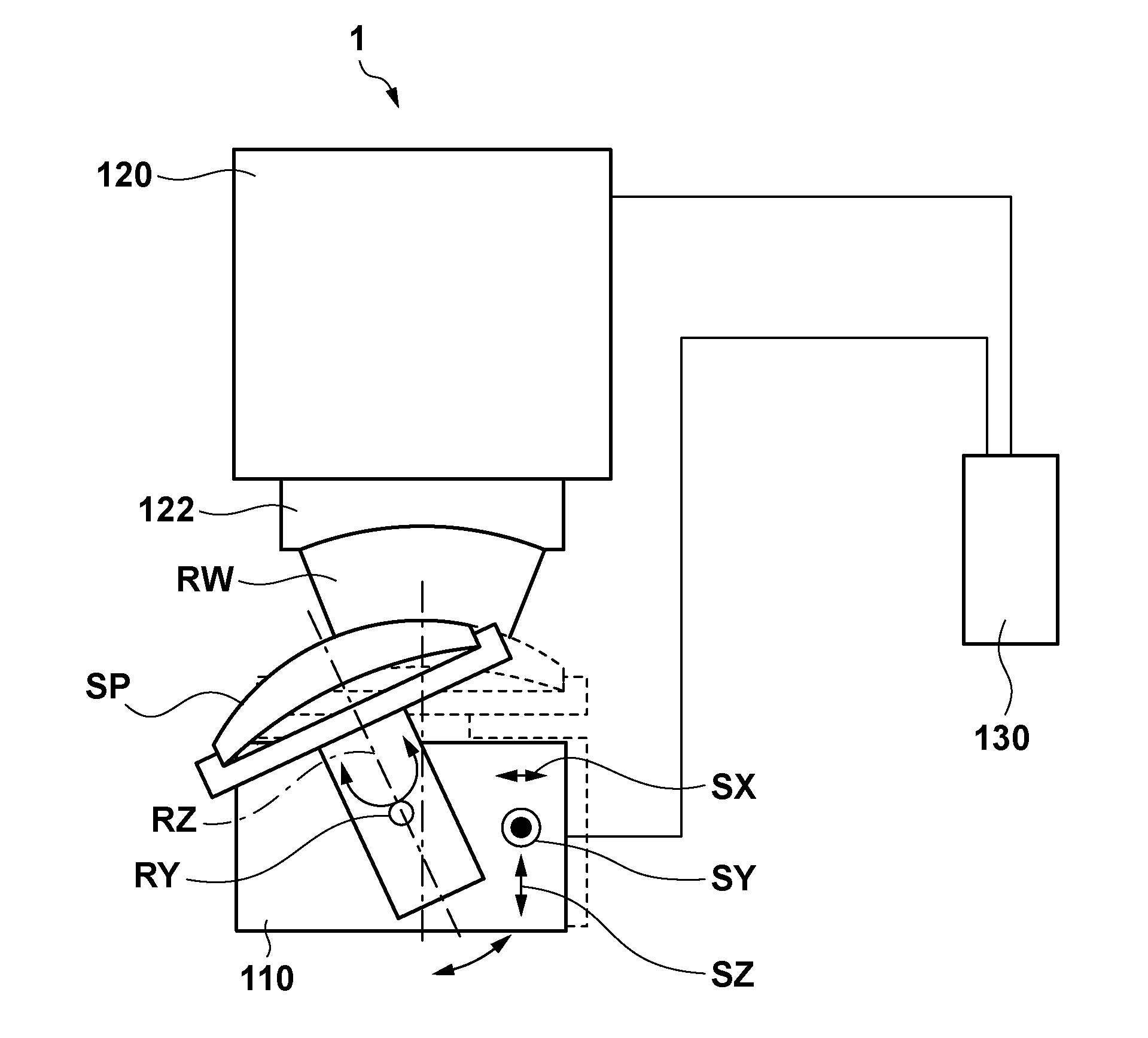
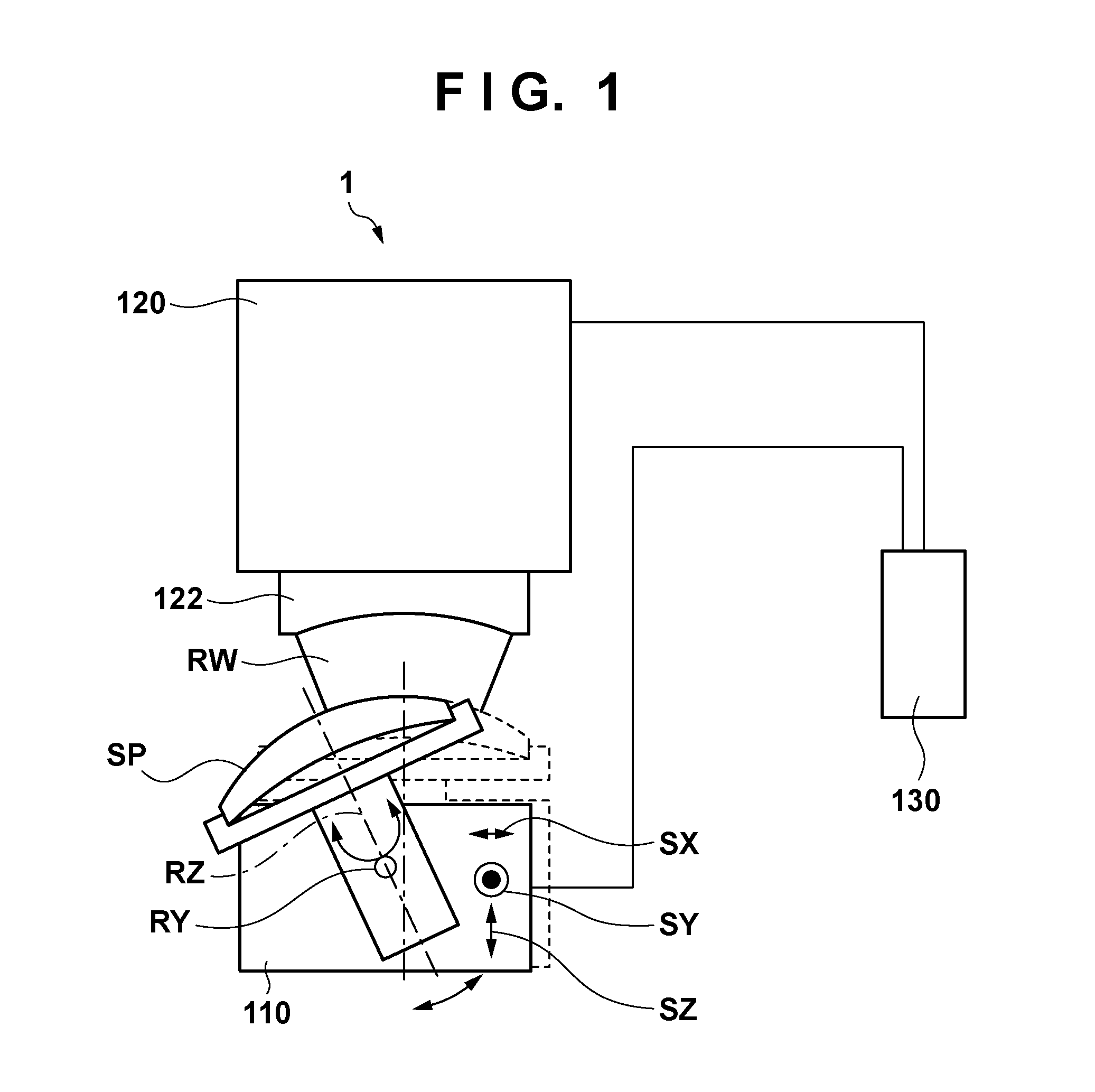
[0024]FIG. 1 is a schematic view showing the arrangement of a measurement apparatus 1 according to one aspect of the present invention. The measurement apparatus 1 includes a stage 110 for holding a measurement target object including a measurement target surface SP having a circular contour, an interferometer 120 including a transmission sphere 122, and a control unit 130 for controlling the measurement apparatus 1 as a whole.
[0025]The stage 110 has, as movable axes, a tilt axis RY about which the measurement target surface SP is tilted, a stage rotation axis RZ about which the measurement target surface SP rotates, and translation axes SX, SY, and SZ with respect to which the measurement target surface SP is translated. The interferometer 120 detects interference fringes between light reflected by the reference surface of the transmission sphere 122 and light RW reflected by the measurement target surface SP (more specifically, one of a plurality of partial regions set to cover th...
second embodiment
[0048]In the first embodiment, a method of selecting, from the plurality of partial regions, at least three partial contour regions which are equiangularly positioned from the center of the measurement target surface SP, and obtaining, based on the shape data of the partial contour regions, a rotation axis about which the measurement target surface SP rotates has been described. In this embodiment, a method of selecting at least three partial contour regions (that is, arbitrary partial contour regions) from a plurality of partial regions, and obtaining, based on the shape data of the selected partial contour regions, a rotation axis about which a measurement target surface SP rotates will be described. Assume in this example that three partial contour regions are selected.
[0049]FIG. 9 is a view for explaining calibration of the rotation axis of the shape data of the partial regions. FIG. 9 shows the relationship between the rotation axis about which the measurement target surface SP...
third embodiment
[0059]Although in the first embodiment, coordinate transformation is performed for the shape data of each partial region in step S310, it is not always necessary to perform coordinate transformation for the shape data of each partial region. If coordinate transformation is not performed for the shape data of each partial region, the shape data of the partial region indicates a shape obtained by observing a circular contour from diagonally above, which is an ellipse, as described above. Note that the flattening is not such large, and the shape may be approximately regarded as a circle.
[0060]In this embodiment, a rotation axis about which a measurement target surface SP rotates is obtained by considering the contour as a circle without performing coordinate transformation for the shape data of each partial region. As described above, if an elliptic arc is approximated by a circular arc, the radius of a circle C shown in FIG. 9 is different from that when coordinate transformation is p...
PUM
 Abstract
Description
Claims
Application Information