Voltage Source Converter And A Method For Fault Handling Thereof

a voltage source converter and fault handling technology, applied in the direction of d ac network circuit arrangement, active power filtering, etc., can solve the problems of affecting the operation of the bypass switch, and affecting the operation of the entire vcs, so as to delay the activation of the bypass switch, reduce the number of redundant cell modules, and reduce the effect of conduction loss

Inactive Publication Date: 2013-01-31
ABB POWER GRIDS SWITZERLAND AG
View PDF6 Cites 53 Cited by
  • Summary
  • Abstract
  • Description
  • Claims
  • Application Information

AI Technical Summary

Benefits of technology

[0018]With the failure of one of the first and second converter units another failure in the still healthy converter unit would jeopardize the functionality of the entire voltage source converter. To avoid an emergency shut-down of the voltage source converter, the bypass switch is provided to bypass the load current and accordingly to ensure a possibility to continue operation of the voltage source converter. However, the bypass switch can be a simple mechanical closing switch with no special requirements on speed of operation etc. owing to the second redundant converter unit and its overloading capacity which will ensure a maintained current path for the load current. Once the bypass switch has been closed it will not be opened again. A mechanical bypass switch has the advantage of low conduction losses, however semiconductor switches such as IGBTs and MOSFETs can be used.
[0019]According to an embodiment of the invention the control unit includes a fault detecting unit adapted to detect the presence of a failure in one of the converter units and upon detecting that the failure has disappeared the control unit is configured to control the valves according to the first switching pattern. The fault detecting unit will detect the presence of a fault based on information provided by available sensors included in the control unit. If the failure disappears the control unit has a possibility to resume the first switching pattern as long as the cell is not bypassed by the bypass switch. This is an advantage since the number of redundant cell modules is limited and there is a need for a certain number of cell modules in operation to maintain the desired voltage level.
[0020]According to an embodiment of the invention the control unit is adapted to generate said triggering signal to the bypass switch at a certain time after the occurrence of a failure has been detected in any of the first and second converter units. The load current through the still healthy converter unit will increase after the occurrence of the failure and thus the temperature will also increase. If said healthy converter unit exceeds its thermal limit there is a risk of a failure also in the still healthy converter unit. On the other hand, it is an advantage to delay the activation of the bypass switch as long as possible for reasons mentioned above. A convenient way to accomplish such a delay is by generating the triggering signal to the bypass switch a certain time after the occurrence of the failure has been detected.
[0021]According to an embodiment of the invention the control unit is adapted to generate said triggering signal to the bypass switch when the temperature of the at least one cell module exceeds a threshold value. By measuring the temperature of the cell module, the optimal delay of the bypass activation switch can be more accurately determined.

Problems solved by technology

As a large number of cells may be used in series to achieve the ac-voltage level of the transmission line or distribution line, a failure in a single cell module could lead to a necessitated shut-down of the entire VCS if no measures is taken.
A problem with mentioned solutions for bypassing failed cell modules is the interruption of the load current i.e., the delay between the failure of the cell module and the bypass performed by the switch.
When a cell module fails and goes into an open circuit the load current is interrupted which in combination with a high circuit loop inductance will result in a high voltage across the cell module and extreme energy development which could destroy adjacent equipment.

Method used


Image

  • Voltage Source Converter And A Method For Fault Handling Thereof
  • Voltage Source Converter And A Method For Fault Handling Thereof
  • Voltage Source Converter And A Method For Fault Handling Thereof

Examples


Embodiment Construction

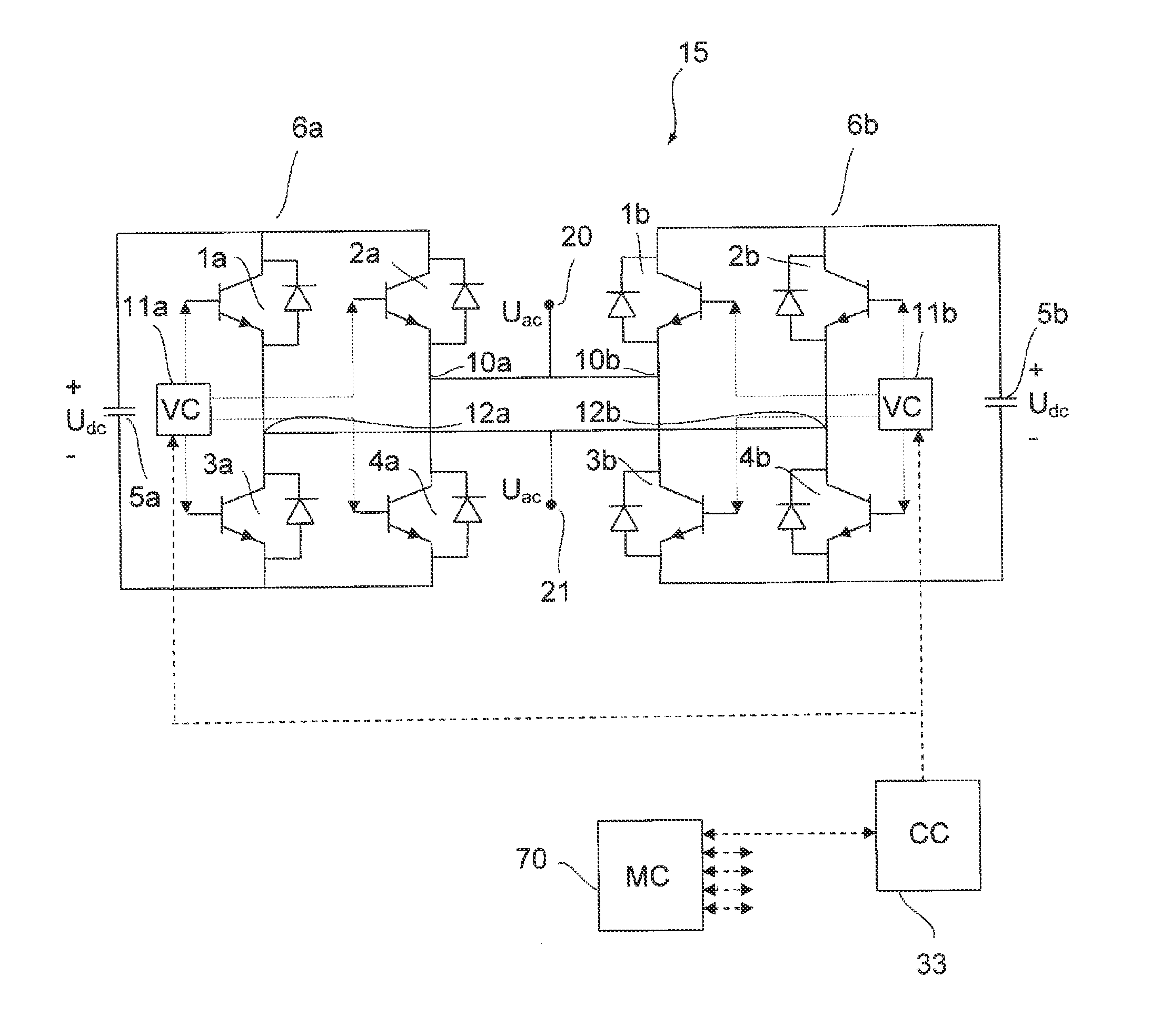
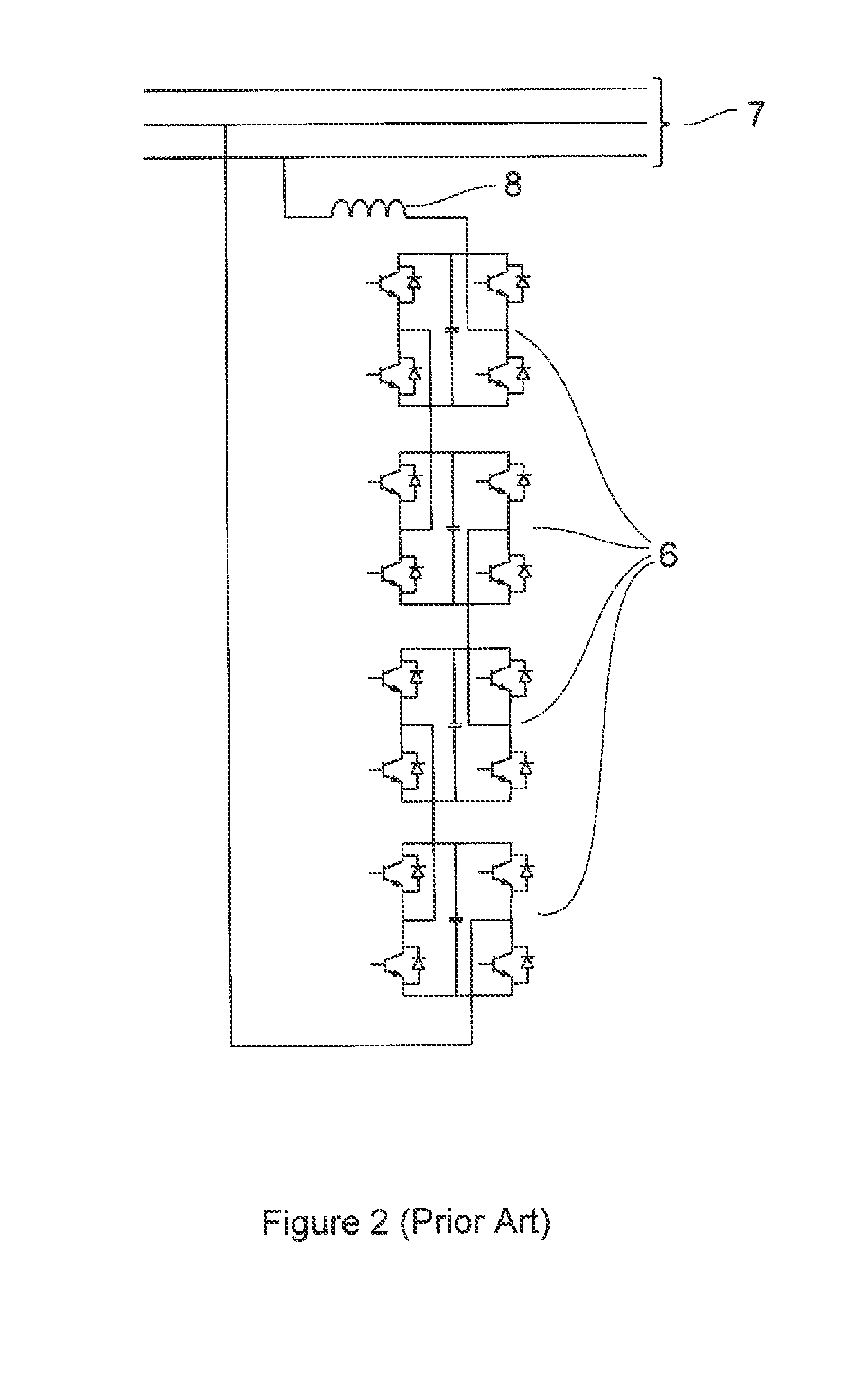
[0057]FIG. 3 illustrates a three-phase voltage source converter 22 according to an embodiment of the invention and a high voltage transmission line or medium voltage distribution line 7 to which the voltage source converter is connected. The invention is however not restricted to voltage source converters having three phases. The voltage source converter 22 can be connected in a delta or a wye arrangement. Each phase includes a plurality of cell modules 31 and a line inductor 8 connected in series. The line inductor 8 is needed for current control and filtering purposes. The number of cell modules varies and can be more than one hundred. The voltage source converter 22 further includes a control unit adapted to control the output voltage of each cell module 31 and thus the voltage of the voltage source converter which is the sum of the voltage of each series-connected cell module 31. The control unit includes a main controller 70, a plurality of cell controllers 32 and a plurality o...


PUM


Abstract

A voltage source converter having a plurality of cell modules connected in series, each cell module including a converter unit having an ac-side and a dc-side, and the voltage source converter includes a control unit adapted to control the converter units, where at least one of the cell modules includes a second redundant converter unit having an ac-side which is connected in parallel with the ac-side of the first converter unit and the control unit is configured to substantially synchronously control the first and the second converter units.

Description

FIELD OF THE INVENTION[0001]The present invention relates to a voltage source converter having a plurality of cell modules connected in series, each cell module comprising a converter unit having an ac-side and a dc-side, and the voltage source converter comprises a control unit adapted to control the converter units. The present invention further relates to a method for fault handling of a cell module in a voltage source converter.BACKGROUND OF THE INVENTION[0002]Within flexible alternating current transmission systems (FACTS) a plurality of control apparatus are known. One such FACTS apparatus is a static compensator (STATCOM). A STATCOM comprises a voltage source converter (VSC) having an ac-side connected to a high voltage transmission line or a medium voltage distribution line in an electrical power system and a dc-side connected to a temporary electric power storage means such as capacitors. The STATCOM transforms a dc-voltage on its dc-side into an ac-voltage on its ac-side a...

Claims


Application Information

Patent Timeline
Patent Type & Authority Applications(United States)
IPC IPC(8): H02J1/00
CPCH02J3/1842H02J3/1857H02M1/32Y02E40/26H02M7/797H02M2007/4835Y02E40/22H02M7/757H02M7/493Y02E40/20H02M7/4835H02J3/18
Inventor HOSINI, FALAHMONGE, MAURO
Owner ABB POWER GRIDS SWITZERLAND AG
Why Eureka
Try Eureka