Pulsed Plasma Generator

a generator and plasma technology, applied in the field of pulsed plasma generators, can solve the problems of additional non-value impacts, limited methods of generating these types of voltage pulses, and limited energy storage capacity of bipolar capacitors described in the prior art with respect to high levels of energy storag

Active Publication Date: 2013-01-31
ROSENER KIRK
View PDF7 Cites 4 Cited by
  • Summary
  • Abstract
  • Description
  • Claims
  • Application Information

AI Technical Summary

Problems solved by technology

However his methods of generating these types of voltage pulses were limited by inductive constraints of the types of power transformers that he used to create voltage pulses for his bremsstrahlung photon experiments.
The energy storage capacity of bipolar capacitors described in the prior art with respect to high levels of energy storage is also limited by the internal break

Method used


Image

  • Pulsed Plasma Generator
  • Pulsed Plasma Generator
  • Pulsed Plasma Generator

Examples


Embodiment Construction

FIG. 1 Through FIG. 5—Preferred Embodiment

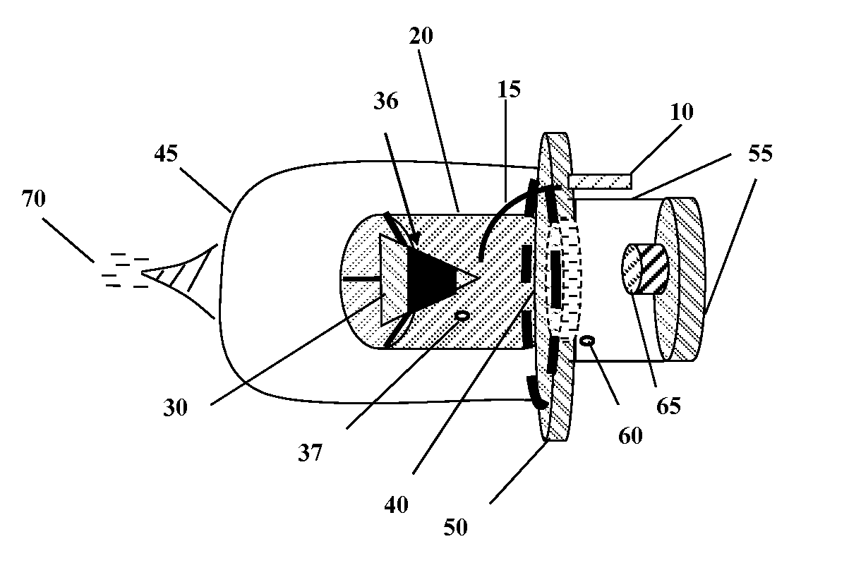
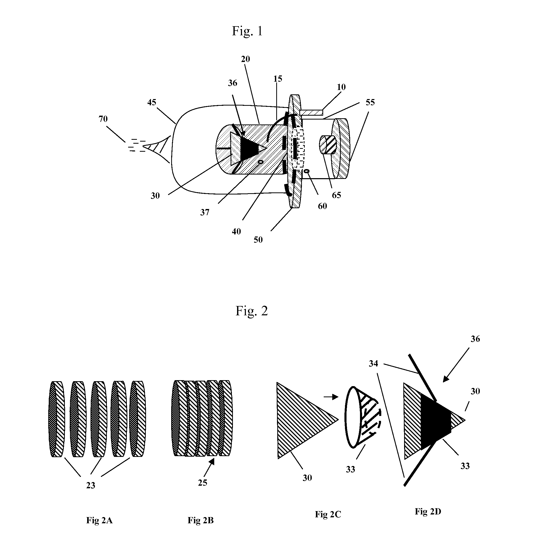
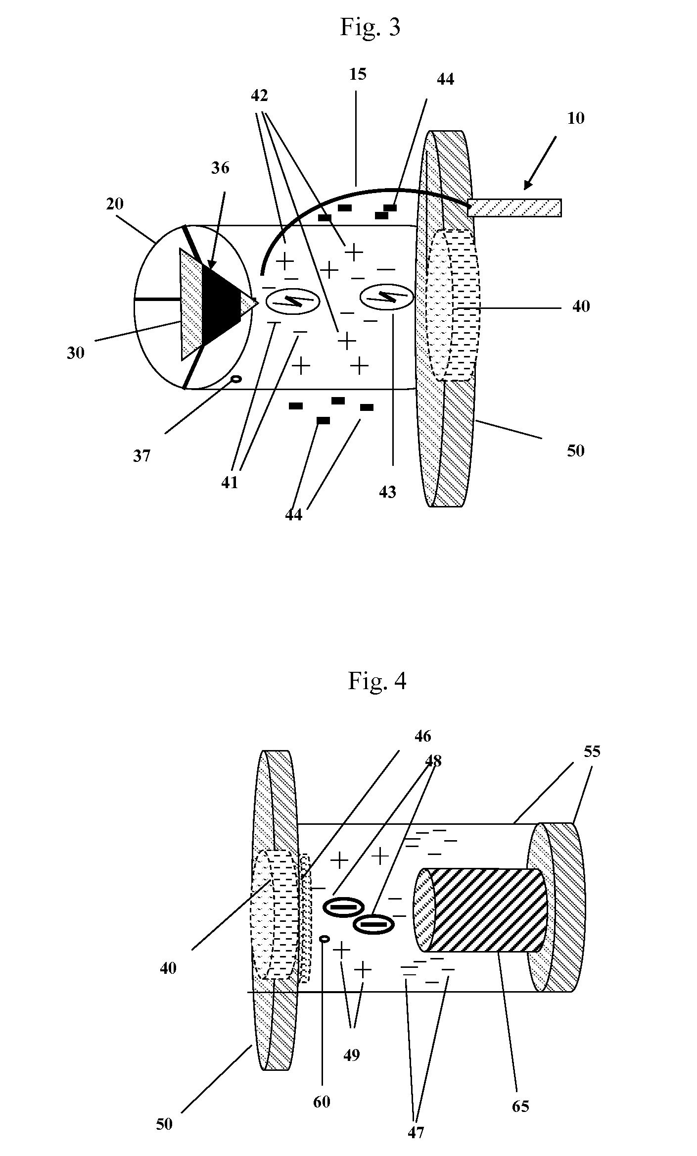
[0067]The preferred embodiment of the PPG invention is to generate slow-speed high energy free electrons. Alternative embodiments include generating a source of high energy positive ions.

[0068]In FIG. 1 a voltage multiplier (10) is connected to one end of a conductor (15). Conductor (15) is inserted through an outer Faraday shield mounting plate (50) and into a first chamber (20). In FIG. 3 a tip of the conductor (15) is pointed directly towards one end a unipolar piezoelectric capacitor (30), this end being in the shape of a sharp point. A gap distance exists between the tip of the conductor (15) and the sharp point of a unipolar piezoelectric capacitor (30) where this gap distance allows an optimal flow of electrons from the tip of the conductor (15) and the sharp point of the unipolar piezoelectric capacitor (30) in the form of a brush or corona discharge when the voltage multiplier (10) is energized.

[0069]FIG. 2 provides a depiction of t...


PUM


Abstract

A pulsed electrostatic/electric field generator apparatus providing a source of large quantity, free slow-speed high energy free electrons, or high energy positive ions, contained in an electrostatic/electric field capacity exceeding 1 Joule. The pulsed electrostatic/electric field generator apparatus encapsulates an enclosed non-equilibrium, non-thermal pulsed power plasma. A key subcomponent of this apparatus incorporates an innovative unipolar piezoelectric capacitor creating high voltage nanosecond rise time pulses in a multistage high energy step-up pulsed plasma generation sequence of steps. The resulting multi-Joule electrostatic/electric field is then tapped to provide a source of current and/or potential for use by external loads.

Description

CROSS-REFERENCE TO RELATED APPLICATIONS[0001]NONEFEDERALLY SPONSORED RESEARCH[0002]NOT APPLICABLESEQUENCE LISTING OR PROGRAM[0003]NOT APPLICABLEBACKGROUND OF THE INVENTION[0004]1. Field of Invention[0005]The Pulsed Plasma Generator (PPG) is a high-voltage generator producing electrons, or positive ions, through a multi-stage, non-equilibrium, non-thermal, non-magnetic pulsed plasma method using externally provided energy. Energy pulse events occur through a multi-stage energy concentration sequence within the apparatus. This sequence includes methods to concentrate electrostatic / electric energy that is subsequently released from a uniquely designed electron emissive device. The timed release of the concentrated electron energy from the electron emissive device is in the form of a plurality of non-nuclear energetic electrons. These electrons drive subsequent events creating bremsstrahlung photons interacting within molecules residing within a compressed gas. Results of these interact...

Claims


Application Information

Patent Timeline
IPC IPC(8): H05H1/24
CPCH05H2001/481H05H1/48H05H1/47H01J37/32073
Inventor ROSENER, KIRK W.
Owner ROSENER KIRK
Why Eureka
Try Eureka