Control device that detects whether or not irreversible demagnetization has occurred in permanent magnet of permanent magnet synchronous motor

a control device and permanent magnet technology, applied in the direction of motor/generator/converter stopper, electronic commutator, dynamo-electric converter control, etc., can solve the problems of inability to specify, deterioration of track precision, broken driven object, etc., to reduce the operation range of permanent magnet synchronous motor, appropriately detect irreversible demagnetization in the magnet

Active Publication Date: 2013-01-31
FANUC LTD
View PDF3 Cites 13 Cited by
  • Summary
  • Abstract
  • Description
  • Claims
  • Application Information

AI Technical Summary

Benefits of technology

[0015]According to an aspect of the present invention, the estimated torque constant relating to the permanent magnet synchronous motor is calculated from the current representative value and the acceleration representative value acquired from a plurality of current values and a plurality of acceleration values in the same operation state over a plurality of periods of the sinusoidal command signal and the predetermined inertia relating to the permanent magnet synchronous motor, and whether or not irreversible demagnetization has occurred in the permanent magnet of the permanent magnet synchronous motor is detected based on the difference between the estimated torque constant and the predetermined torque constant relating to the permanent magnet synchronous motor. Due to this, the permanent magnet synch

Problems solved by technology

In such a case, it is not possible for the permanent magnet synchronous motor to generate a predetermined torque, and therefore, the actual track of movement of a driven object, that is operated by the permanent magnet synchronous motor, deviates from the track of movement of the driven object commanded by an upper control device, such as a CNC (computer numerical control), and there is a possibility that the track precision deteriorates and the driven object is broken under certain circumstances.
Due to this, when the operation range of the drive shaft of the permanent magnet synchronous motor is limited, such as when the driven object is moved along an arc using the permanent magnet synchronous motor in a mac

Method used


Image

  • Control device that detects whether or not irreversible demagnetization has occurred in permanent magnet of permanent magnet synchronous motor
  • Control device that detects whether or not irreversible demagnetization has occurred in permanent magnet of permanent magnet synchronous motor
  • Control device that detects whether or not irreversible demagnetization has occurred in permanent magnet of permanent magnet synchronous motor

Examples


first embodiment

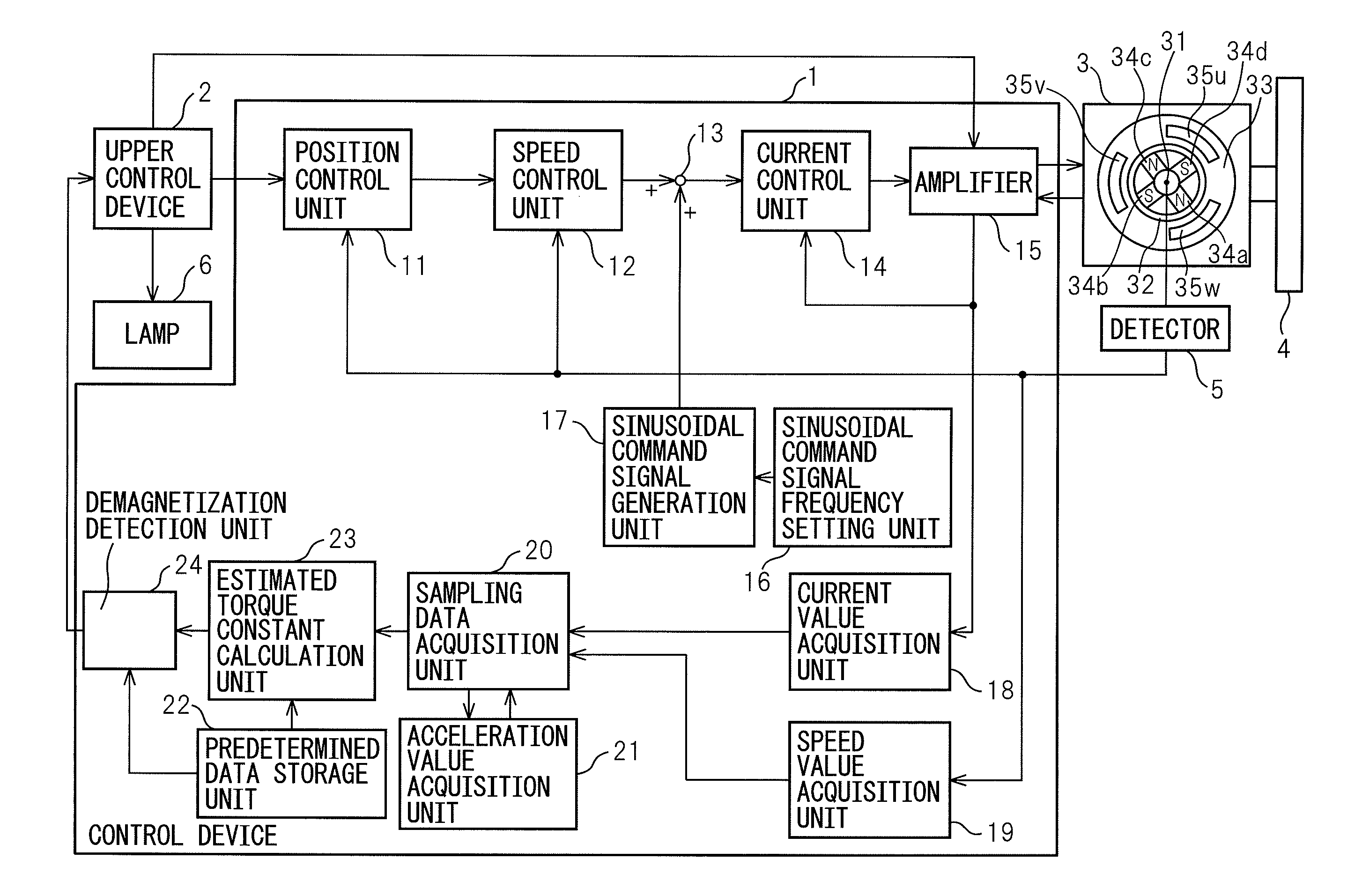
[0022]Referring to the drawings, FIG. 1 is a block diagram of a system having a control device of the present invention. In FIG. 1, a control device 1 controls the position, speed, torque, etc., of a permanent magnet synchronous motor 3 based on a command signal in accordance with a work process instructed by an upper control device 2, such as a CNC (computer numerical control) connected to the control device 1. By controlling the control device 1, a driven object 4 such as a table connected to the permanent magnet synchronous motor 3, an arm connected thereto and a work attached thereto and detached therefrom performs a predetermined motion (for example, arc motion).

[0023]In order for the control device 1 to control the position, speed, torque, etc., of the permanent magnet synchronous motor 3, there is provided a detector 5 configured to detect the speed (rotating speed) of the permanent magnet synchronous motor 3 and to supply the detected speed to the control device 1. For examp...

second embodiment

[0053]FIG. 3 is a block diagram of a system having a control device of the present invention. In FIG. 3, a control unit 1′ further comprises a friction calculation unit 25, a corrected current value generation unit 26, and an offset component removal unit 27 in addition to the components of the control unit in FIG. 1.

[0054]The friction calculation unit 25 calculates friction (viscous friction and coulomb friction) in accordance with the speed value or the polarity of speed acquired in the speed value acquisition unit 19. The corrected current value generation unit 26 corrects the current value acquired in the current value acquisition unit 18 in accordance with the friction calculated in the friction calculation unit 25 and generates a corrected current value. The offset component removal unit 27 removes an offset component of the corrected current value generated in the corrected current value generation unit 26. The offset component removal unit 27 includes, for example, a high-pa...

third embodiment

[0057]FIG. 4 is a block diagram of a system having a control device of the present invention. In FIG. 4, a control device 1″ further comprises a reduction rate calculation and speed gain change unit 28 in addition to the components of the control device 1 in FIG. 1.

[0058]The reduction rate calculation and speed gain change unit 28 calculates a reduction rate a according to the expression σ=Ks / Kt and changes the speed gain of the permanent magnet synchronous motor 3 based on the reduction rate σ. For example, the reduction rate calculation and speed gain change unit 28 changes a speed integral gain K1 and a speed proportional gain K2 according to the expressions K1=K1 / σ and K2=K2 / σ, respectively.

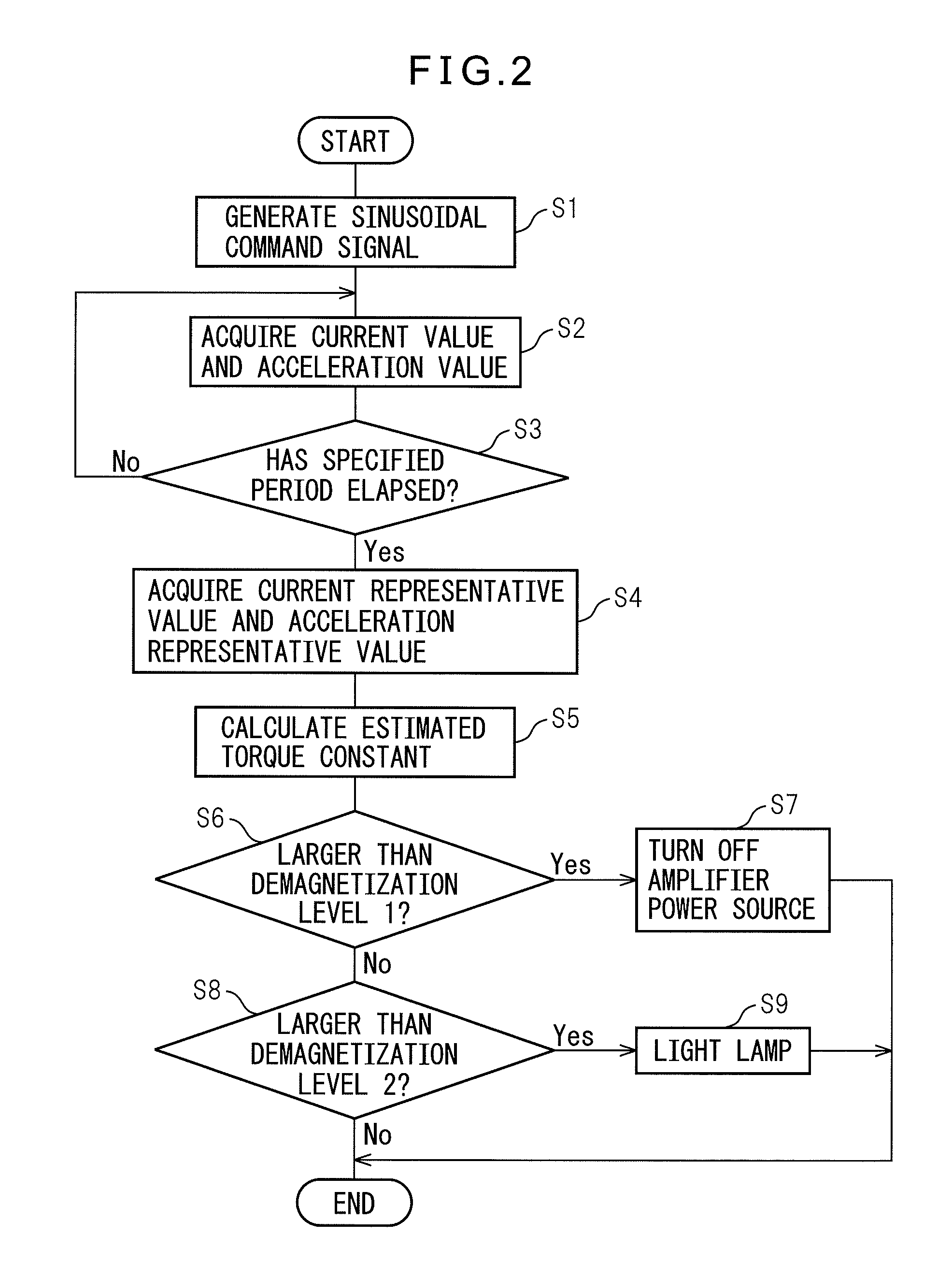
[0059]The calculation of the reduction rate a and the change of the speed gain by the reduction rate calculation and speed gain change unit 28 are performed in step S9 of the flowchart in FIG. 2.

[0060]According to the present embodiment, when the difference between the estimated torque consta...


PUM


Abstract

An estimated torque constant calculation unit calculates an estimated torque constant relating to the permanent magnet synchronous motor from a current representative value and an acceleration representative value acquired from a plurality of current values and a plurality of acceleration values in the same operation state over a plurality of periods of a sinusoidal command signal and a predetermined inertia relating to the permanent magnet synchronous motor. A demagnetization detection unit detects whether or not irreversible demagnetization has occurred in the permanent magnet of the permanent magnet synchronous motor based on a difference between the estimated torque constant and a predetermined torque constant relating to the permanent magnet synchronous motor.

Description

BACKGROUND OF THE INVENTION[0001]1. Field of the Invention[0002]The present invention relates to a control device that detects whether or not irreversible demagnetization has occurred in a permanent magnet of a permanent magnet synchronous motor, which operates a driven object, such as a work and tool, in a machine tool, etc.[0003]2. Description of Related Art[0004]Conventionally, a permanent magnet synchronous motor, such as a rotary servomotor in which a permanent magnet is provided in any one of a stator and a rotor, a liner servomotor in which a permanent magnet is provided in any one of a stator and a slider, and a vibration servomotor in which a permanent magnet is provided in any one of a stator and a vibrator, is widely used in various fields.[0005]In a permanent magnet synchronous motor, there is a case where irreversible demagnetization occurs in a permanent magnet of the permanent magnet synchronous motor due to an abnormal temperature rise of the permanent magnet of the ...

Claims


Application Information

Patent Timeline
IPC IPC(8): H02P6/08H02P6/06H02P6/12H02P6/17H02P6/28
CPCH02P29/028H02P29/02H02P29/032
Inventor SONODA, NAOTOIWASHITA, YASUSUKE
Owner FANUC LTD
Why Eureka
Try Eureka