Distortion compensation for printing

a technology of distortion compensation and printing, applied in printing, printed circuits, electrical devices, etc., can solve the problems of large number of printheads, difficult to compensate for distortion, and many flexible substrates such as plastic substrates, which exhibit significant dimensional changes,

Inactive Publication Date: 2013-01-31
FLEXENABLE LTD
View PDF3 Cites 16 Cited by
  • Summary
  • Abstract
  • Description
  • Claims
  • Application Information

AI Technical Summary

Benefits of technology

[0020]In some preferred embodiments the controller is also configured to compensate for distortions of longitudinal pitch that is distortions of pitch in the printing direction. This may be achieved by outputting data for adjusting or controlling droplet deposition timing. This data may comprise timing signals or, in some preferred embodiments timing adjust signals such as a frequency and / or phase adjust signal or a signal specifying a division ratio for a high frequency signal which is to be divided down to derive print head drive waveforms. Separate timing or timing adjust data may be provided for each print head nozzle in such a way as to facilitate the derivation of nozzle drive signals with appropriate timing from one or a few (for example one per head) variable frequency signal generators.
[0024]In a further aspect the invention provides a method of compensating for pitch distortion of a substrate which is to be written by a direct-write apparatus having at least one direct write head with a plurality of direct-write channels, said pitch distortion comprising distortion of the pitch of a pattern with respect to which said writing is to be aligned, writing with said direct-write channels being performed in accordance with a write drive waveform for each channel, the method comprising: moving at least one of said substrate and said head relative to the other in a writing direction during writing; and altering one or both of a frequency and a phase of each said drive waveform during said writing in response to distortion data providing information on said pitch distortion over a two-dimensional region of said substrate to compensate for pitch distortion in said writing direction.

Problems solved by technology

However, many flexible substrates, such as plastic substrates, exhibit significant dimensional changes when subject to mechanical stress or temperature variations both of which occur during any manufacturing process.
Such distortions cause severe problems in a manufacturing process which requires definition of multiple patterns on top of each other with good registration of the features of an upper pattern to the features of a previously defined pattern.
In the case of a conventional lithographic patterning process with multiple mask levels it is very difficult to compensate for this distortion, particularly if the distortion pattern is not the same every time the process is performed, but changes when environmental conditions, process conditions, or materials properties vary.
A significant drawback of this scheme is that it requires a large number of printheads, and more importantly, a large number of nozzles will not be firing regularly, but will remain idle for significant periods of time.
In the case of inkjet printing, drying of the ink on the nozzle plate is a serious problem, which can cause degradation of the directionality of the droplets emitted from the nozzle, or in the worst case, nozzle blockage.
In the distortion compensation scheme of FIG. 1 this requirement is difficult to meet.

Method used


Image

  • Distortion compensation for printing
  • Distortion compensation for printing
  • Distortion compensation for printing

Examples


Embodiment Construction

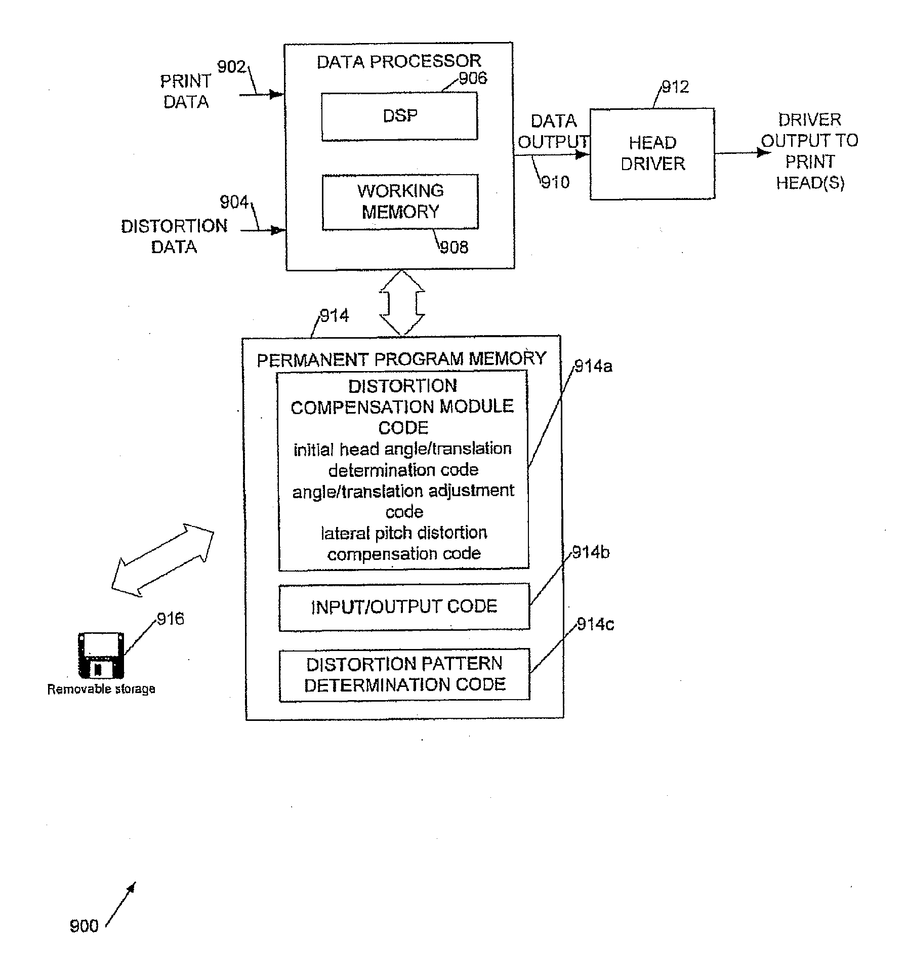
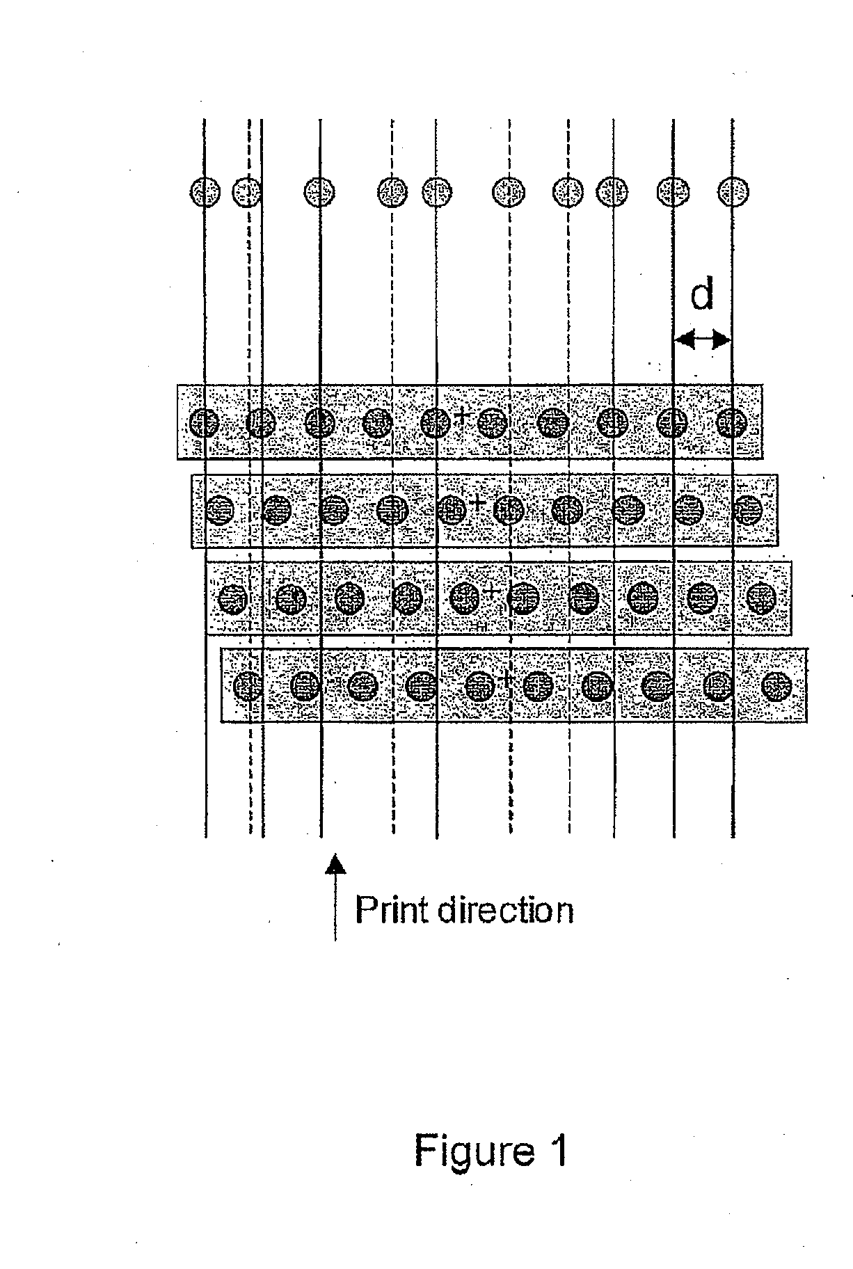
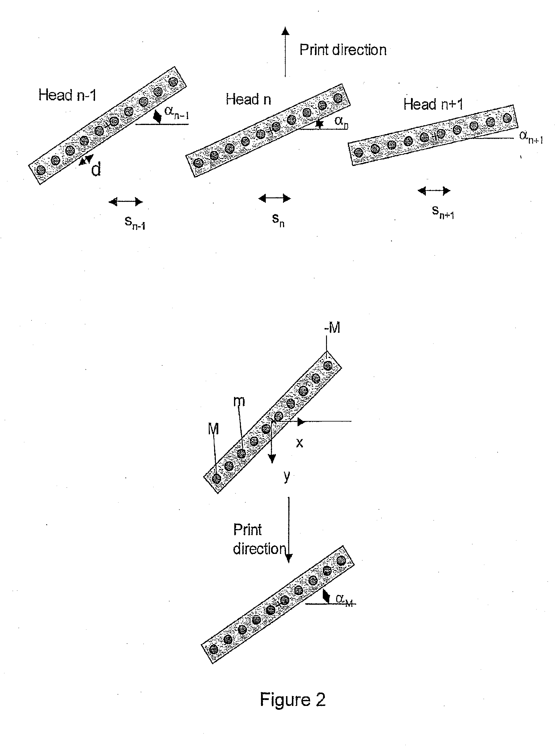
[0036]Broadly, we will describe a printing machine comprising a substrate, and at least one printhead with at least two material deposition channels which are movable with respect to the substrate, wherein the printhead is mounted on a stage which allows rotation of the printhead around an axis perpendicular to the substrate and translation in a direction perpendicular to the print direction, and wherein during each print swath, the rotation angle and translation values of the printhead are varied in order to change the pitch and the lateral position in the direction perpendicular to the print direction of material deposited from the different deposition channels; and an algorithm which computes the required rotation angles and translation values for a given pattern of substrate distortion.

[0037]More particularly we will describe a distortion compensation procedure for a multiple-nozzle, multiple-head direct-write printer which enables compensation of a range of arbitrary distortion...


PUM


Abstract

A printing machine includes a substrate and at least one printhead with at least two material deposition channels which are movable with respect to the substrate, wherein the printhead is mounted on a stage which allows rotation of the printhead around an axis perpendicular to the substrate and translation in a direction perpendicular to the print direction, and wherein during each print swath, the rotation angle and translation values of the printhead are varied in order to change the pitch and the lateral position in the direction perpendicular to the print direction of material deposited from the different deposition channels; and an algorithm which computes the required rotation angles and translation values for a given pattern of substrate distortion.

Description

CROSS-REFERENCE TO RELATED APPLICATIONS[0001]This application is a divisional of U.S. patent application Ser. No. 11 / 720,430, filed May 23, 2008 and incorporated in its entirety by reference herein, which is the U.S. National Phase under 35 U.S.C. §371 of International Application No. PCT / GB2005 / 050201, filed Nov. 10, 2005, designating the United States and published in English on Jun. 1, 2006, as WO 2006 / 056808, which claims priority to United Kingdom Application No. 0426126.9, filed Nov. 29, 2004 and United Kingdom Application No. 0506613.9, filed Apr. 1, 2005.BACKGROUND OF THE INVENTION[0002]1. Field of the Invention[0003]This invention relates to apparatus and methods for the manufacturing of functional structures on dimensionally unstable substrates by direct-write printing techniques, in particular the manufacturing of electronic devices on flexible, plastic substrates.[0004]2. Description of the Related Art[0005]Integration of functional, electronic devices onto flexible subs...

Claims


Application Information

Patent Timeline
Patent Type & Authority Applications(United States)
IPC IPC(8): B41J29/38
CPCB41J2/2146H05K3/125H04N1/409
Inventor SIRRINGHAUS, HENNINGWATTS, JAMES D.
Owner FLEXENABLE LTD
Why Eureka
Try Eureka