Method and apparatus for inspection of light emitting semiconductor devices using photoluminescence imaging

a technology of light-emitting semiconductors and photoluminescence imaging, which is applied in the direction of individual semiconductor device testing, instruments, television systems, etc., can solve the problems of requiring additional tools, slow probing, and damage to leds, and achieve the effect of quick and reliable measurement of light power emitted

Active Publication Date: 2013-01-31
KLA TENCOR TECH CORP
View PDF5 Cites 36 Cited by
  • Summary
  • Abstract
  • Description
  • Claims
  • Application Information

AI Technical Summary

Benefits of technology

[0010]It is an object of the invention to provide a method for quickly and reliably measure the light power emitted by an LED duri

Problems solved by technology

This has several disadvantages: LEDs may get damaged durin

Method used


Image

  • Method and apparatus for inspection of light emitting semiconductor devices using photoluminescence imaging
  • Method and apparatus for inspection of light emitting semiconductor devices using photoluminescence imaging
  • Method and apparatus for inspection of light emitting semiconductor devices using photoluminescence imaging

Examples


Embodiment Construction

[0048]Same reference numerals refer to same elements throughout the various figures. Furthermore, only reference numerals necessary for the description of the respective figure are shown in the figures. The shown embodiments represent only examples of how the invention can be carried out. This should not be regarded as limiting the invention. The description below refers to LED die / chips which should not be regarded as a limitation of the invention. It is evident for any person skilled in the art that the present invention is applicable to light emitting semiconductor material in general.

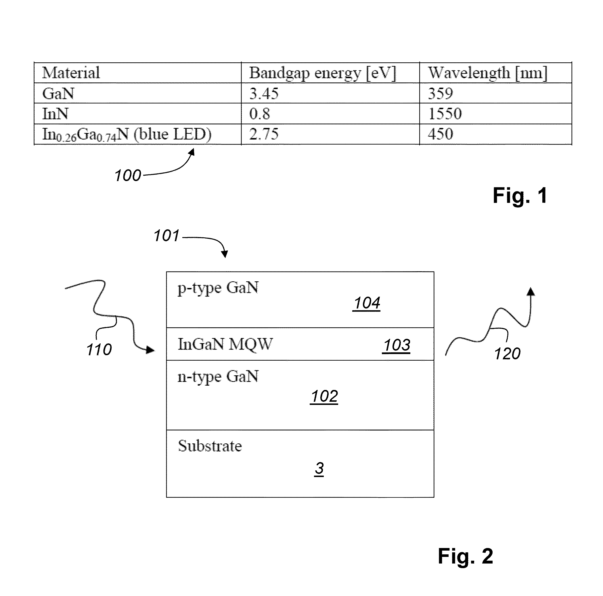
[0049]FIG. 1 is a table 100 showing the bandgap and corresponding wavelength of a III-N semiconductor material system. All semiconductor materials exhibit the so-called photoluminescence effect. This effect is seen when the material is illuminated with light of a certain wavelength, and the photons in the light beam will bring electrons from a low energy state to a high energy state (will generate e...


PUM


Abstract

A method and apparatus for the inspection of light emitting semiconductor devices. The semiconductor device is illuminated with a light source, wherein at least an area of the light emitting semiconductor is illuminated with a waveband of light. The waveband of light λA+λB can generate electron-hole pairs in the light emitting semiconductor to be inspected. Through an objective lens at least a part of the light λC emitted by the light emitting semiconductor is detected. The emitted light is captured with a sensor of a camera that is sensitive to wavelengths of the emitted light, wherein the wavelength of the emitted light is above the width of the waveband. The data of the emitted light, captured with the sensor, are transmitted to a computer system for calculating inspection results of the light emitting semiconductor.

Description

CROSS REFERENCE TO RELATED APPLICATIONS[0001]This patent application claims priority of U.S. provisional patent application No. 61 / 500,987 filed Jun. 24, 2011, the application is incorporated herein by reference.FIELD OF THE INVENTION[0002]The present invention relates to a method for inspection of light emitting semiconductor devices during and after a production process. The light emitting semiconductor devices can be LEDs.[0003]The present invention also relates to an apparatus for inspection of light emitting semiconductor devices on a substrate.BACKGROUND OF THE INVENTION[0004]Solid state lighting (SSL) has several advantages compared to conventional lighting. Main advantages are low power consumption, long lifetime, and small form factor. An important element of SSL is the LED (Light-Emitting Diode) die / chip. Basis for LEDs is a semiconductor material that is undergoing a complex production process in order to obtain a LED. Several metrology and inspection steps are done durin...

Claims


Application Information

Patent Timeline
IPC IPC(8): H04N7/18
CPCG01R31/2635G01N21/6489G01R31/2656H01L33/0095
Inventor BOEYKENS, STEVENMARIVOET, TOM
Owner KLA TENCOR TECH CORP
Why Eureka
Try Eureka