Spread illuminating apparatus

Active Publication Date: 2013-01-31
MINEBEAMITSUMI INC
View PDF3 Cites 5 Cited by
  • Summary
  • Abstract
  • Description
  • Claims
  • Application Information

AI Technical Summary

Benefits of technology

[0020]Each of the above present embodiments is allowed to provide a spread illuminating apparatus excellent in even brightness near

Problems solved by technology

However, particularly in a case of JP-A No. 2008-170739 where a thin-type spread illuminating apparatus has an inclined face in the vicinity of the light incident face, there is a problem that leaked light occurs with a gr

Method used


Image

  • Spread illuminating apparatus
  • Spread illuminating apparatus
  • Spread illuminating apparatus

Examples


Embodiment Construction

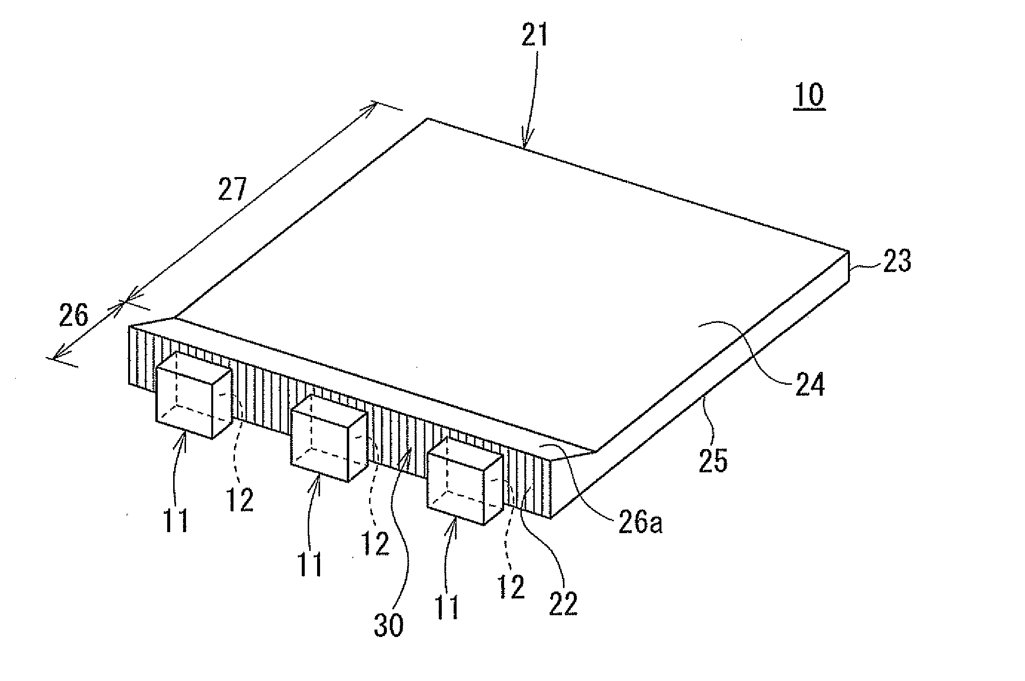
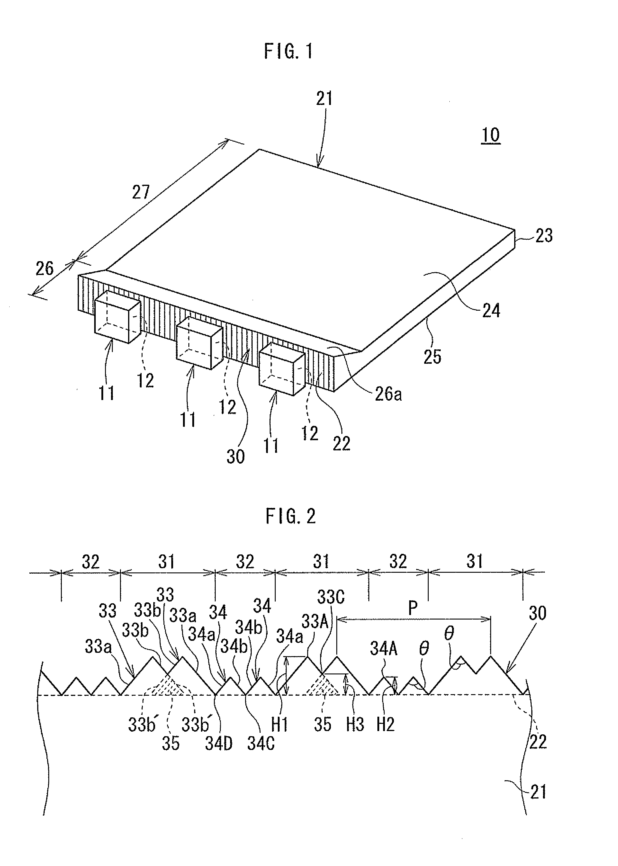
[0025]Hereinafter, embodiments of the present invention will be explained with reference to the accompanying drawings. FIG. 1 is a perspective view illustrating the main portion of a spread illuminating apparatus 10 of one embodiment of the present invention. The spread illuminating apparatus 10 includes: a plurality of LEDs 11 (three LEDs in the illustrated example) as point light sources; and a light guiding plate 21 for planarly exiting out light that has been emitted from the LEDs 11. The LEDs 11 are typically pseudo white color LEDs. The light guiding plate 21 is made of a transparent material (for example, polycarbonate resin) and formed into a substantially rectangular shape in a top view. One side end face of the light guiding plate 21 is a light incident face 22. The LEDs 11 are arranged along the light incident face 22 such that their light emitting faces 12 direct toward the light incident face 22 of the light guiding plate 21.

[0026]Here, a direction moving from the light...


PUM


Abstract

A spread illuminating apparatus includes a point light source; a light guiding plate having a light incident face on which the point light source is mounted, and a light output face. The light incident face has light incident prisms diffusing light emitted from the point light source into a planar space substantially parallel with the light output face. The light incident prisms include: a first prism portion including a plurality of first prisms convex relative to the light incident face; and a second prism portion including a second prism convex relative to the light incident face, the second prism portion being placed next to the first prism portion in a longitudinal direction of the light incident face. The first prism partially overlaps another first prism adjacent thereto, and the vertex of each first prism is set higher than the vertex of the second prism relative to the light incident face.

Description

BACKGROUND OF THE INVENTION[0001]1. Field of the Invention[0002]The present invention relates to a spread illuminating apparatus, and more particularly to a sidelight-type spread illuminating apparatus including a light guiding plate with a light source provided on a light incident face of the light guiding plate. In the spread illuminating apparatus, planar illumination light is adapted to exit out from a light output portion of the light guiding plate.[0003]2. Description of Related Art[0004]In a lighting device provided with a liquid crystal display panel, a sidelight-type spread illuminating apparatus (backlight) having compact, environmentally-compatible LEDs, the LEDs being arranged along the light incident face of a light guiding plate, has been widely applied. This type of spread illuminating apparatus has particularly been used in the field of compact portable information devices such as mobile phones. It is known that, in such a spread illuminating apparatus, uneven bright...

Claims


Application Information

Patent Timeline
IPC IPC(8): F21V13/02
CPCG02B6/0028G02B6/0016
Inventor SUMA, AKIKO
Owner MINEBEAMITSUMI INC
Why Eureka
Try Eureka