
Path switching system, path switching method, and mobile terminal

a switching system and path technology, applied in the field of telecommunications, can solve the problems of conventional technique not giving a detailed description of the indication between the mme and the pdn-gw, degrading the quality of user's call, and income loss for the cellular communications operator

Active Publication Date: 2013-01-31
PANASONIC INTELLECTUAL PROPERTY CORP OF AMERICA
View PDF6 Cites 50 Cited by
  • Summary
  • Abstract
  • Description
  • Claims
  • Application Information

AI Technical Summary

Benefits of technology

The present invention provides a system, method, and mobile terminal for switching between multiple relay devices in a network to manage communication sessions between a mobile terminal and another device. The invention allows for the consideration and performance of additional connections of the mobile terminal to the network, and provides a way for the mobile terminal to determine and process information on the additional connections based on information from different communication sessions. This improves the efficiency and reliability of the network, and ensures that the mobile terminal can offload from one network to another while maintaining optimal performance.

Problems solved by technology

In the 3GPP system, since the MME and the PDN-GW do not work with each other, a problem may arise when the MME triggers the offload of the UE to another PDN-GW.
The quality of user's call is degraded, and in some cases, this leads to an income loss for the cellular communications operator.
However, this conventional technique does not give a detailed description on an indication between the MME and the PDN-GW at the time when the UE has been offloaded.
However, it seems that always monitoring and comparing all the data sessions on various interfaces of the UE increases the requirements to be processed in the UE.

Method used


Image

  • Path switching system, path switching method, and mobile terminal
  • Path switching system, path switching method, and mobile terminal
  • Path switching system, path switching method, and mobile terminal

Examples


first embodiment

General Logic of UE Upon Triggering Offload

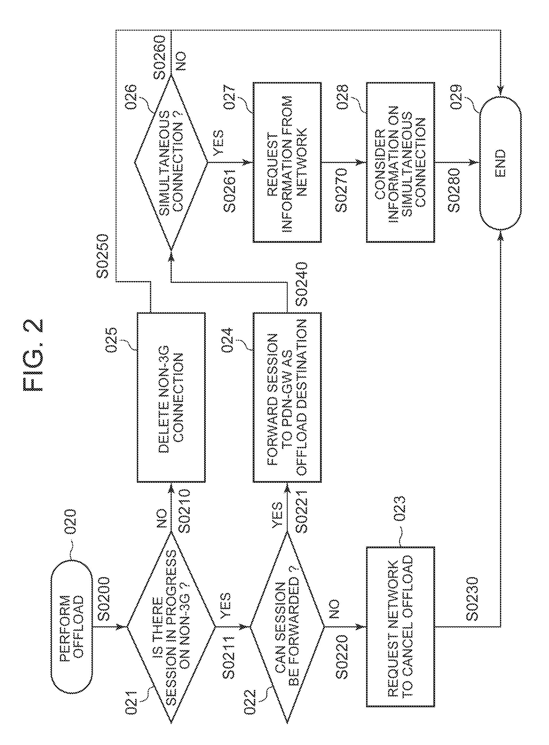
[0052]When the UE receives a notification from the network that the UE has been offloaded to another PDN-GW, a decision function in the UE is required to decide on the influence of the offload on the connection in progress held by the UE at present. FIG. 2 is a flowchart related to a type of decision made by the UE to determine the influence when offload has been performed.

[0053]In this embodiment, when the UE 0100 receives a notification from the network that an IF 01000 of the UE 0100 has been offloaded from a PDN-GW 0104 to an L-GW 0108, this function is started (020), or when the UE 0100 considers that the network has offloaded the IF 01000 of the UE 0100 from the PDN-GW 0104 to the L-GW 0108, this function is started. The UE 0100 may determine that the offload has been performed when a prefix assigned to the UE 0100 has been changed. This function further proceeds (S0200) to check whether there is a data session (data flow) in progress...

second embodiment

Procedure for UE to Terminate Connection with n3G

[0061]As shown in FIG. 2, there are several decisions made by the UE when the UE has been offloaded from the first PDN-GW to the second PDN-GW. FIG. 3 shows a message sequence for describing one result of decision made by the UE.

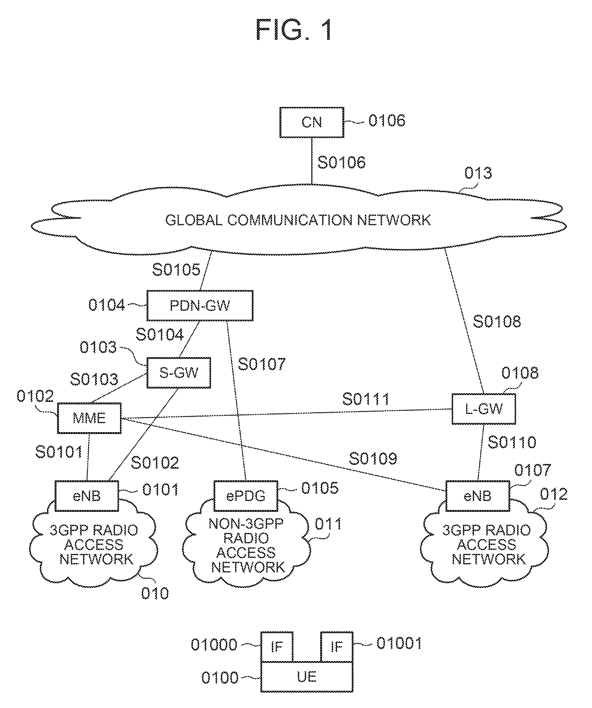
[0062]In this embodiment, it is assumed that both interfaces (IF 01000 and IF 01001) of the UE 0100 do not exchange any data packet at all. It is also assumed that both interfaces of the UE 0100 are connected to the PDN-GW 0104. The IF 01000 is connected to the PDN-GW 0104 through the S-GW 0103 (S0300). The IF 01001 is connected to the PDN-GW 0104 through the ePDG 0105 (S0301). Further, it is assumed that the UE 0100 has moved to an area outside of a tracking area specified by the network. In a 3GPP system, the network defines an area called a tracking area. When the UE is located within a specific tracking area, there is no need to update the network about the location of the UE. When the UE moves away from t...

third embodiment

Procedure for UE to Forward Session Successfully Through SCTP

[0072]As shown in FIG. 2, there are several decisions made by the UE when the UE has been offloaded from the first PDN-GW to the second PDN-GW. FIG. 4 shows a message sequence for describing another result of decision made by the UE.

[0073]In this embodiment, it is assumed that both interfaces (IF 01000 and IF 01001) of the UE 0100 are connected to the PDN-GW 0104. The IF 01000 is connected to the PDN-GW 0104 through the S-GW 0103 (S0300). The IF 01001 is connected to the PDN-GW 0104 through the ePDG 0105 (S0301). It is also assumed that the UE 0100 has only one active data session on the IF 01001 at present. The UE 0100 does not exchange any data packet on the IF 01000. Further, it is assumed that the UE 0100 has moved to an area outside of a tracking area specified by the network. In a 3GPP system, the network specifies a specific tracking area for the UE. When the UE is located within the specified tracking area, the UE ...


PUM


Abstract

A path switching system is provided, in which when UE has been offloaded from a first PDN-GW to a second PDN-GW, if there is an additional connection of the UE to the first PDN-GW, processing related to the additional connection can be performed on the UE side. The system includes: a control unit for sending a mobile terminal a message including information indicative of having switched relay devices, which relay a packet between the mobile terminal and a communication device, from a first relay device to a second relay device; and the mobile terminal for determining whether there is an added path other than part of a path from the mobile device before movement to the communication device and capable of being managed by the control unit, established between the mobile terminal and the first relay device, and when there is the added path, performing processing on the added path.

Description

TECHNICAL FIELD[0001]The present invention relates to the field of telecommunications for packet exchange data communication networks, and particularly to a path switching system, a path switching method, and mobile terminal for switching paths to exchange packets between the mobile terminal and a communication device as a communication partner according to movement of the mobile terminal.BACKGROUND ART[0002]The Third Generation Partnership Project (3GPP) has developed the standard for a system, newly named as EPS (Evolved Packet System), in which a long term evolution (LTE) program provides improved spectral efficiency, reduced latency, and improvement in use of radio resources. The EPS allows users to experience high data-rate and abundant applications and services at lower cost than before. To obtain connectivity to the EPS, users have to get user equipment (UE) based on LTE. From the recent market trends, it has been considered that the UE would support multiple different radio ...

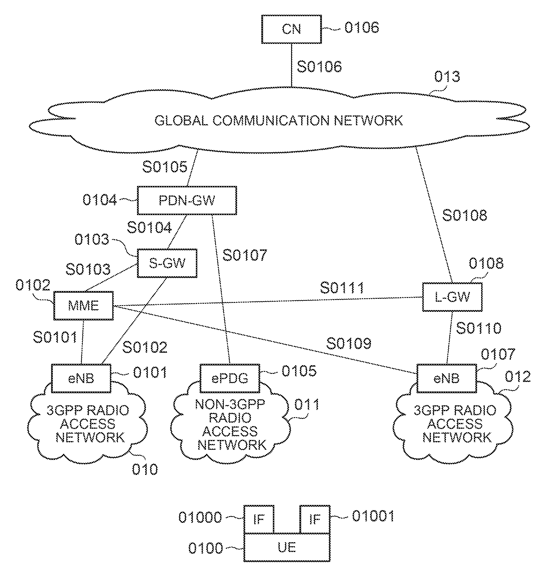
Claims


Application Information

Patent Timeline
Patent Type & Authority Applications(United States)
IPC IPC(8): H04W76/00H04B7/14
CPCH04W36/12H04W88/16H04W84/047H04W76/02H04W76/10
Inventor LIM, CHUN KEONG BENJAMINNG, CHAN WAHJEYATHARAN, MOHANA DHAMAYANTHICHENG, HONGASO, KEIGOAOYAMA, TAKAHISAIKEDA, SHINKICHI
Owner PANASONIC INTELLECTUAL PROPERTY CORP OF AMERICA
Learn More