

Exhaust gas purifying apparatus for internal combustion engine
a technology for exhaust gas purification and internal combustion engines, which is applied in the direction of machines/engines, electric control of exhaust treatment, separation processes, etc., can solve the problems of inefficient heat exchange between exhaust gases, failure to recover adsorption capability, and insufficient recovery of adsorption capability of exhaust gases. , to achieve the effect of increasing exhaust resistance and sufficient recovery of adsorption capability
- Summary
- Abstract
- Description
- Claims
- Application Information
AI Technical Summary
Benefits of technology
Problems solved by technology
Method used
Image

Examples
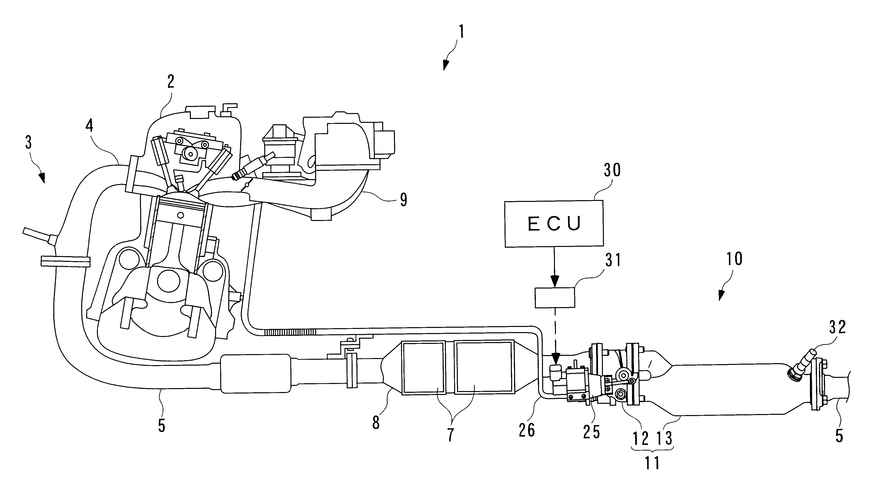
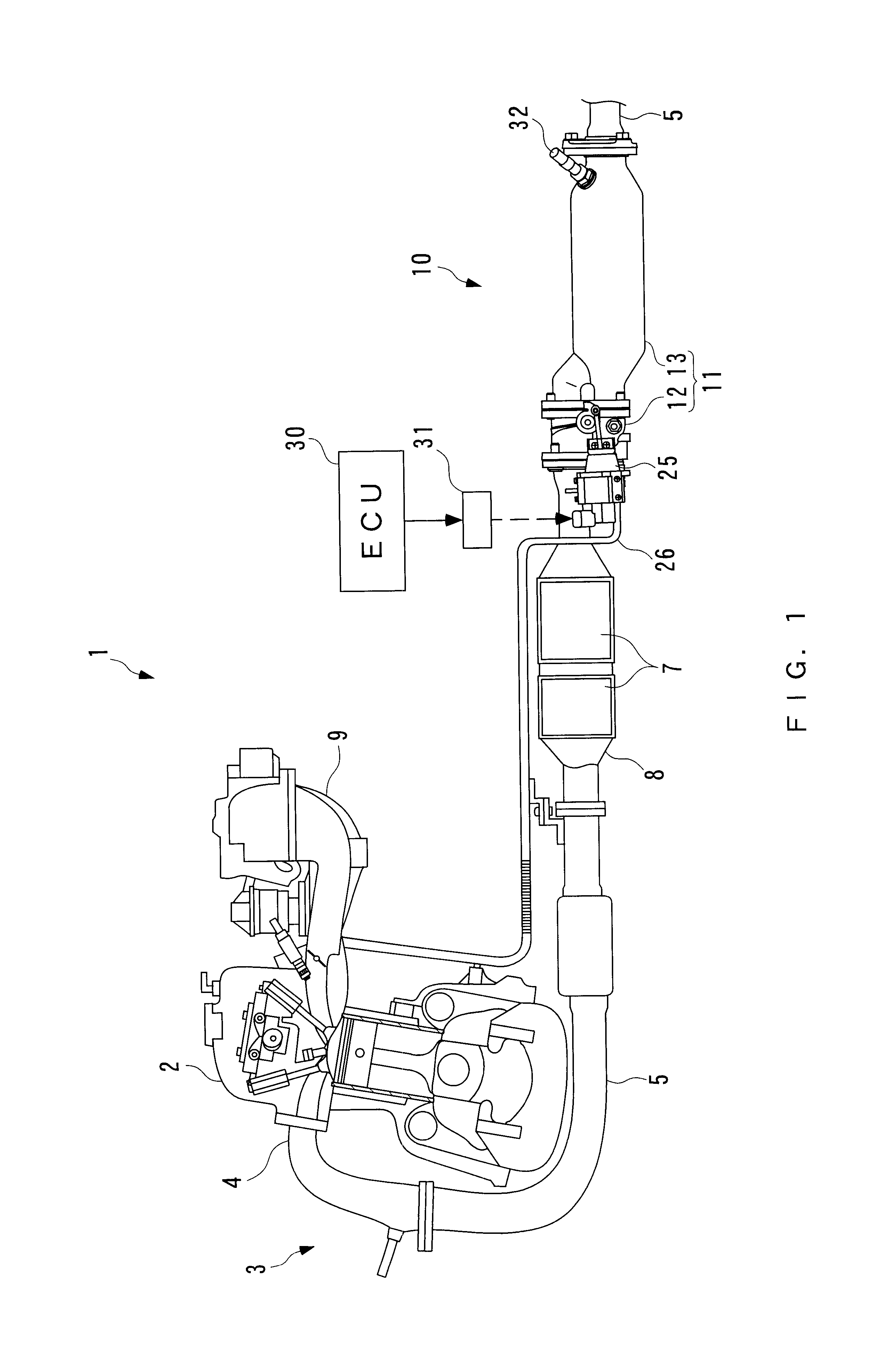
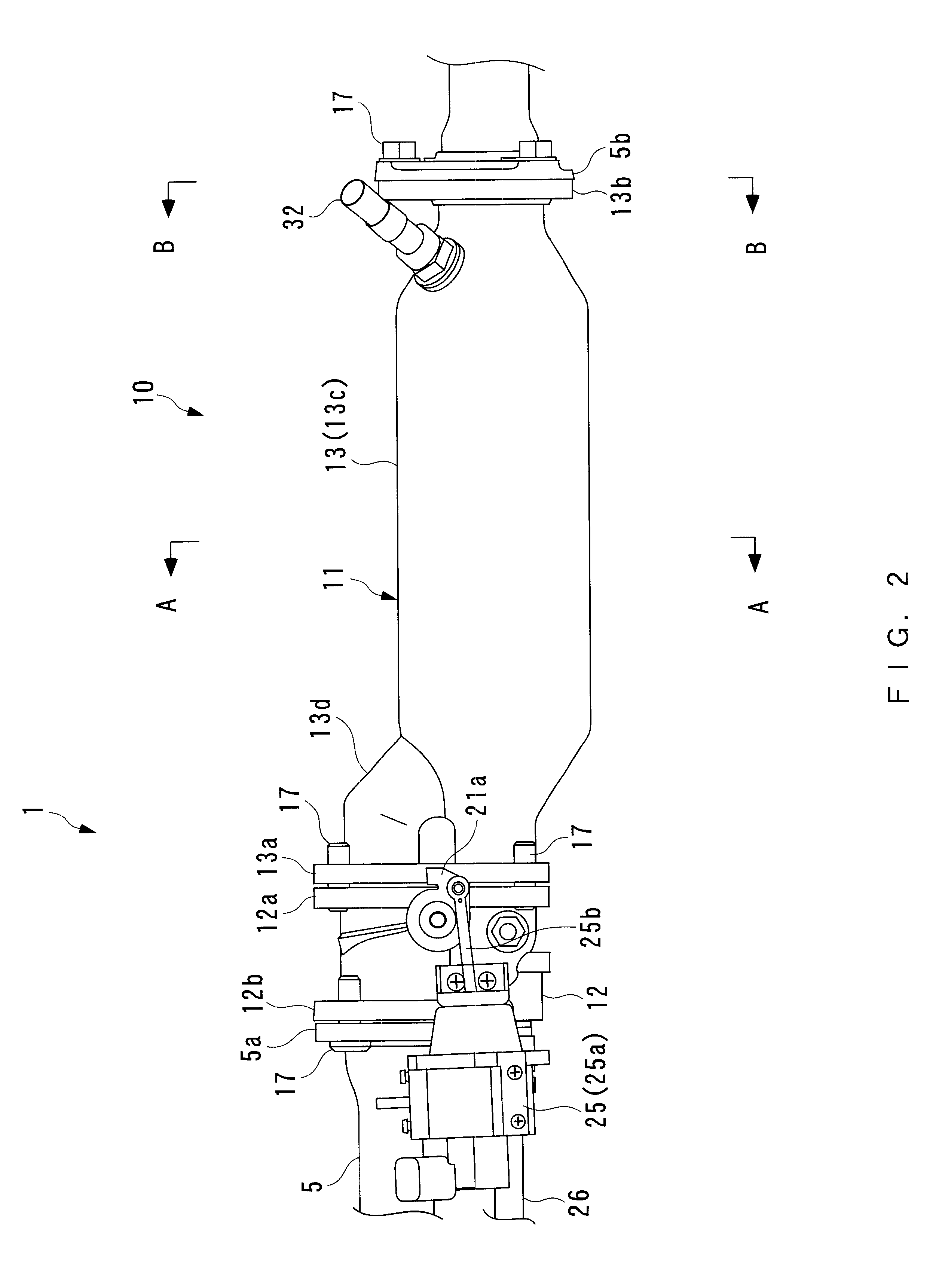
case 11
The case 11 is composed of a branch case 12 and a junction case 13 arranged in combination at a location downstream of the branch case 12, which are integrally assembled into the The branch case 12 and junction case 13 are both made of a metal (for example, stainless steel). These branch case 12 and junction case 13 are provided with flanges 12a, 13a, respectively, formed on their end faces adjacent to each other. These flanges 12a, 13a are fixed by three bolts 17 to connect the branch case 12 to the junction case 13. Likewise, the branch case 12 is connected to the upstream exhaust pipe 5 through flanges 12b, 5a formed on their end faces adjacent to each other with three bolts 17, while the junction case 13 is connected to the downstream exhaust pipe 5 through flanges 13b, 5b formed on their end faces adjacent to each other with three bolts 17.
The main exhaust passage 14 extends through the branch case 12, and an upstream end of the bypass exhaust passage 15 is branched off an ups...
PUM
 Abstract
Description
Claims
Application Information