Spatial prediction method, image decoding method, and image coding method

a prediction method and image technology, applied in the field of spatial prediction method in coding and decoding an image, can solve the problems of low spatial prediction efficiency, low overall compression gain, and high variation of the resulting bit rate, and achieve the effect of reducing the complexity of spatial prediction

Active Publication Date: 2013-01-31
SUN PATENT TRUST
View PDF4 Cites 27 Cited by
  • Summary
  • Abstract
  • Description
  • Claims
  • Application Information

AI Technical Summary

Benefits of technology

[0038]The spatial prediction method according to the presen

Problems solved by technology

However, the efficiency of the spatial coding is lower than the performance of the temporal coding (inter cod

Method used


Image

  • Spatial prediction method, image decoding method, and image coding method
  • Spatial prediction method, image decoding method, and image coding method
  • Spatial prediction method, image decoding method, and image coding method

Examples


embodiment 1

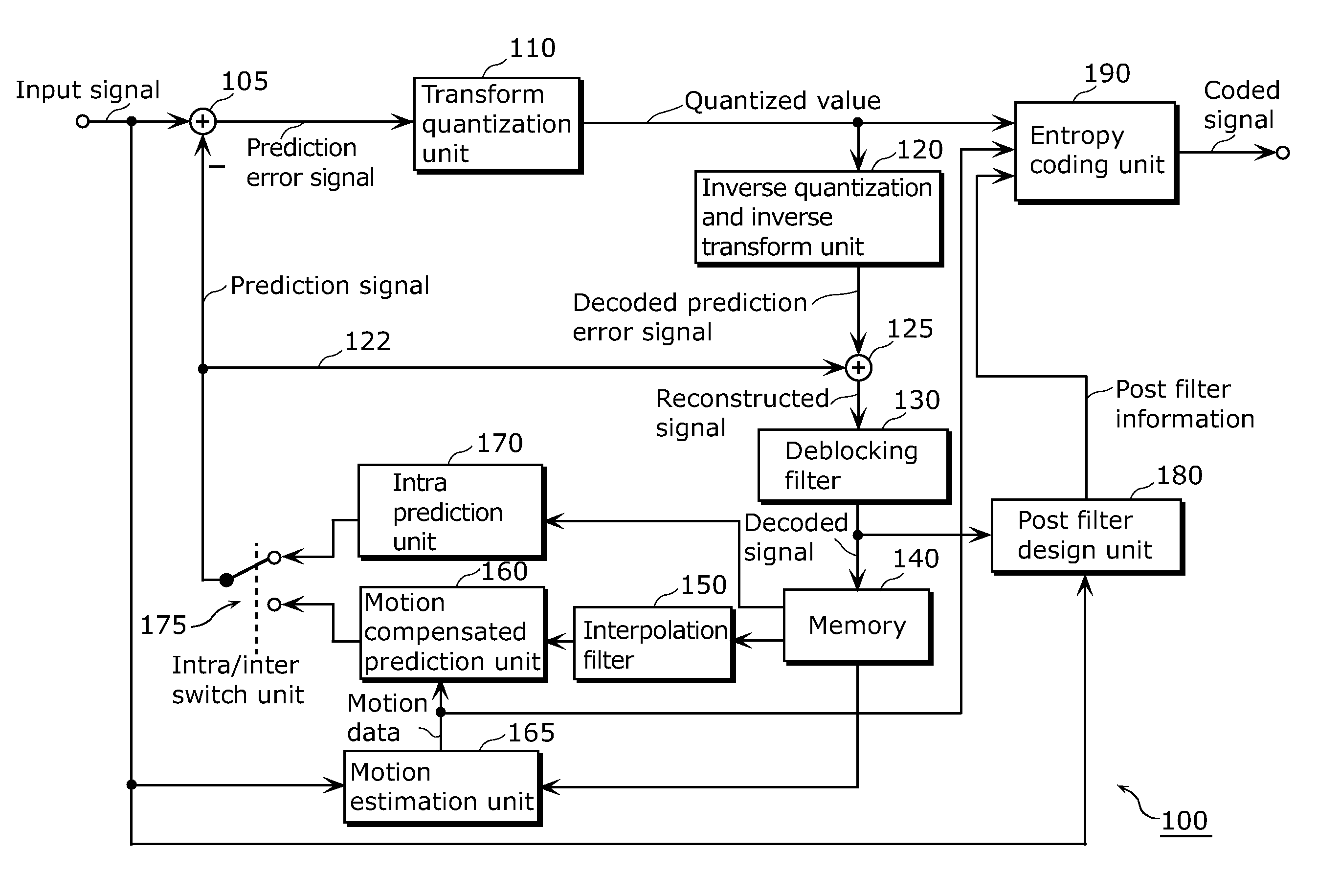
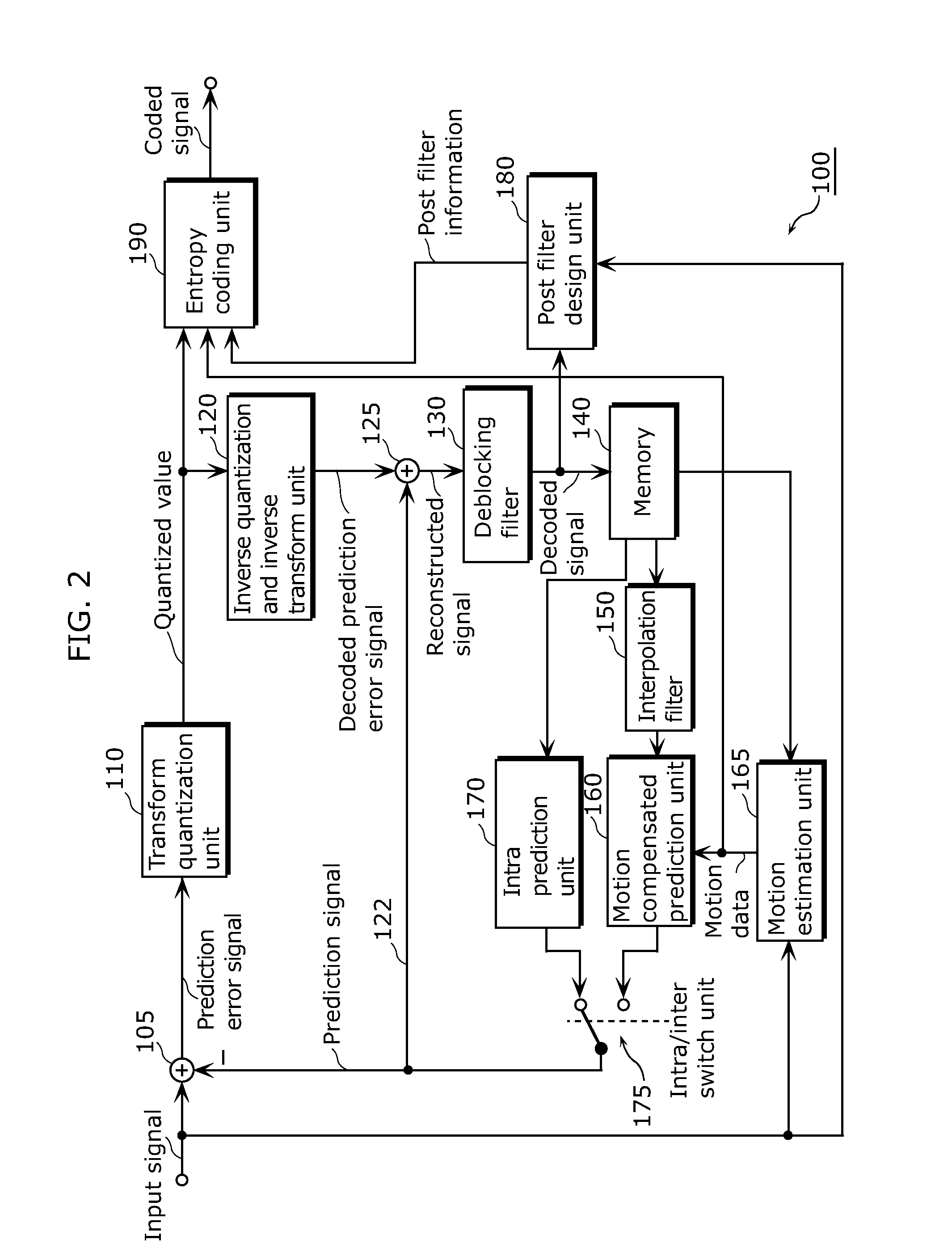
[0071]FIG. 2 is a block diagram illustrating an example of an encoder 100 according to Embodiment 1. The encoder 100 includes a subtracting unit 105, a transform quantization unit 110, an inverse quantization and inverse transform unit 120, an adding unit 125, a deblocking filter 130, a memory 140, an interpolation filter 150, a motion compensated prediction unit 160, a motion estimation unit 165, an intra prediction unit 170, an intra / inter switch unit 175, a post filter design unit 180, and an entropy coding unit 190.

[0072]The subtracting unit 105 first determines differences (prediction error signal, residual signal, or prediction error block) between a current block to be coded of an input video signal (input signal) and a corresponding predicted block (prediction signal) predicted for the current block. The prediction signal (predicted block) is obtained either by a temporal prediction (inter prediction) or by a spatial prediction. The type of prediction can be varied on a per ...

embodiment 2

[0156]An independent computer system can easily perform processing described in each of Embodiments by recording, in a recording medium, a program for implementing the structure of the video coding method (image coding method) or the video decoding method (image decoding method) according to Embodiment 1. The recording medium may be any as long as the program can be recorded therein, such as a magnetic disk, an optical disk, an optical magnetic disk, and a semiconductor memory.

[0157]Hereinafter, applications of the video coding method and the video decoding method according to each of Embodiments, and a system using such applications will be described.

[0158]FIG. 8 illustrates an overall configuration of a content providing system ex100 for implementing content distribution services. The area for providing communication services is divided into cells of desired size, and base stations ex106 to ex110 which are fixed wireless stations are placed in each of the cells.

[0159]The content p...

embodiment 3

[0189]Video data can be generated by switching, as necessary, between (i) the moving image coding method or the moving image coding apparatus shown in each of Embodiments and (ii) a moving image coding method or a moving image coding apparatus in conformity with a different standard, such as MPEG-2, MPEG4-AVC, and VC-1.

[0190]Here, when a plurality of video data that conforms to the different standards is generated and is then decoded, the decoding methods need to be selected to conform to the different standards. However, since to which standard each of the plurality of the video data to be decoded conforms cannot be detected, there is a problem that an appropriate decoding method cannot be selected.

[0191]In order to solve the problem, multiplexed data obtained by multiplexing audio data and others onto video data has a structure including identification information indicating to which standard the video data conforms. The specific structure of the multiplexed data including the vid...


PUM


Abstract

A spatial prediction method capable of reducing the complexity of spatial prediction includes: detecting an edge (E) overlapping the current block by obtaining a horizontal gradient (Gy) and a vertical gradient (Gx) between pixels within a block adjacent to the current block; calculating an integer slope of the edge; determining, for each pixel position within the current block, a sub-pel position being an intersection between (i) a line that has the integer slope and passes through the pixel position and (ii) a boundary of the adjacent block; and predicting, for each pixel position, a pixel value at the pixel position based on a pixel value interpolated in the sub-pel position, wherein the boundary of the adjacent block is a row or a column that is the closest to the current block, among rows or columns of pixels included in the adjacent block.

Description

TECHNICAL FIELD[0001]The present invention relates to a spatial prediction method in coding and decoding an image, and in particular to a directional spatial interpolation involving edge detection or to efficient implementation of such an interpolation.BACKGROUND ART[0002]Spatial prediction methods, that is, spatial interpolation have been employed in many applications. In particular, spatial interpolation forms an essential part of many image and video coding and processing applications. In hybrid image or video coding algorithms, spatial prediction is typically employed for determining a prediction for an image block based on the pixels of already coded / decoded blocks. On the other hand, spatial interpolation may also be used as a part of post processing the decoded image or video signal, in particular for error concealment.[0003]The majority of standardized video coding algorithms are based on hybrid video coding. Hybrid video coding methods typically combine several different lo...

Claims


Application Information

Patent Timeline
IPC IPC(8): G06K9/36H04N19/593
CPCH04N19/136H04N19/44H04N19/14H04N19/593H04N19/11H04N19/176H04N19/42H04N19/182
Inventor DRUGEON, VIRGINIESHIBAHARA, YOUJINISHI, TAKAHIROSASAI, HISAOTANIKAWA, KYOKO
Owner SUN PATENT TRUST
Why Eureka
Try Eureka