Method and System for Detecting Optical Fibre Connection

a technology of optical fibre connection and detection method, applied in the field of communication, can solve the problems of increased workload, increased possibility of error, so as to improve system performance and network stability, and increase the cost of network construction and maintenance

Active Publication Date: 2013-01-31
ZTE CORP
View PDF3 Cites 10 Cited by
  • Summary
  • Abstract
  • Description
  • Claims
  • Application Information

AI Technical Summary

Benefits of technology

[0020]The solutions of the disclosure determine whether the current optical fibre connection relationship information which is reported by the single board is the correct optical fibre connection relationship according to the optical fibre matching connection relationship information of the single board, and put forward effective optical fibre matching connection suggestions if determining that the information is the wrong optical fibre connection relationship. The problem of increased cost for network construction and maintenance caused by wrongly and insufficiently configuring the optical fibre connection via manual configuration in the related technologies can be solved. The system performance and network stability can be improved.

Problems solved by technology

However, the optical fibre connection is likely to be configured wrongly or insufficiently via the manual configuration of the network manager.
Especially, under the condition of large number of network dimensions, large number of the same single boards and large number of ports, the possibility of error becomes higher.
And, because the workload is higher due to more elements, wrong configuration of the optical fibre connection relationship can hardly be detected.
Once the number of elements is increased to dozens or more, it requires very heavy and complicated workload to manually search for the few wrongly-configured or insufficiently-configured optical fibre connections in the hundreds and thousands of optical fibre connections.
In addition, it is hard for the optical fibre connections which are manually configured by the network manager to stay consistent with the actual optical fibre connections, or to be automatically and synchronously updated.
Thus, the cost of network construction and maintenance is increased.

Method used


Image

  • Method and System for Detecting Optical Fibre Connection
  • Method and System for Detecting Optical Fibre Connection
  • Method and System for Detecting Optical Fibre Connection

Examples


embodiment 1

PREFERRED EMBODIMENT 1

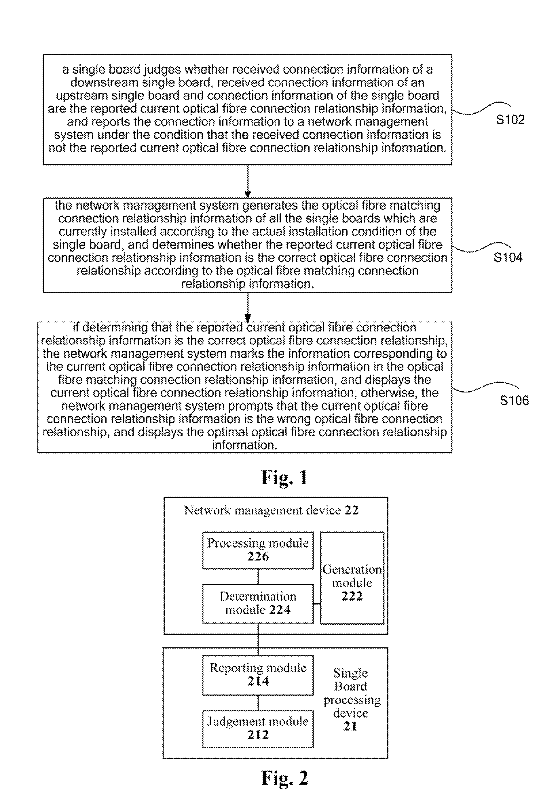
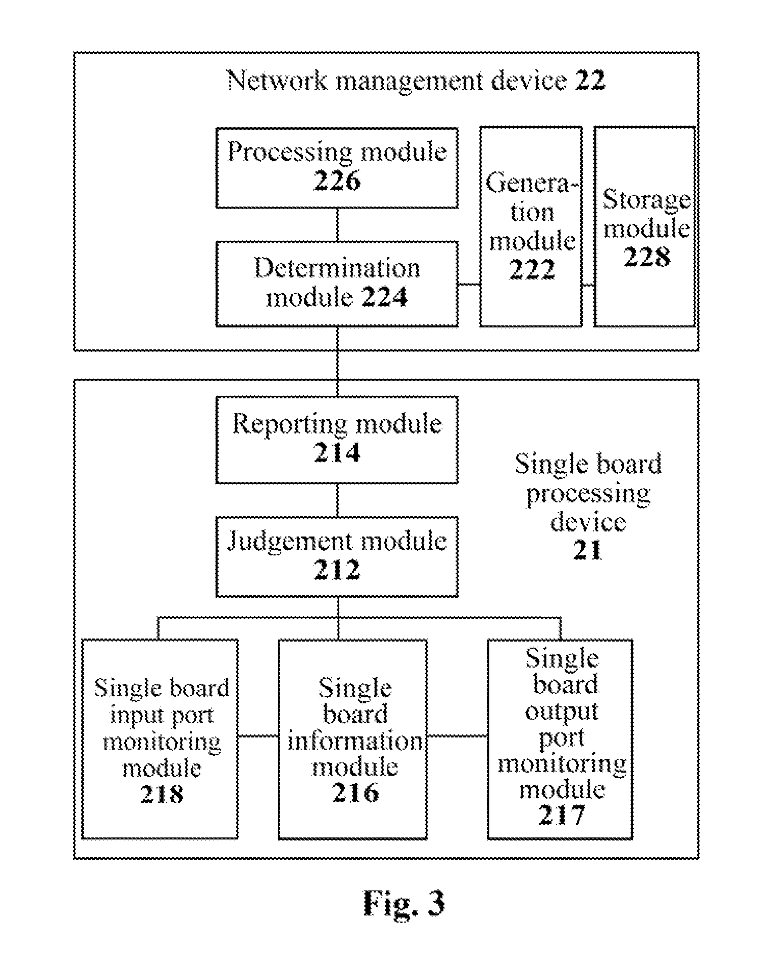
[0060]The system for detecting optical fibre connection (called as fibre connection for short below) according to the preferred embodiment 1 of the disclosure automatically acquires and displays the optical fibre connection of actual physical connection on the network manager, and gives suggestive prompt information for the wrong connection and insufficient connection condition. FIG. 4 shows a diagram of all the modules of a detection system according to the preferred embodiment 1 of the disclosure. As shown in FIG. 4, the detection system comprises: the single board information module 216, the single board output port monitoring module 217, the single board input port monitoring module 218, the single board connection information module 42 and the network management processing module 46. That is, after the actual physical single boards are installed and the optical fibres are connected, the input port monitoring module 218 and the output port monitoring module...

embodiment 2

PREFERRED EMBODIMENT 2

[0090]The preferred embodiment 2, which is applied inside the optical network, can automatically locate the actual optical fibre connection relationship and can prompt the related content after the actual physical optical fibre is connected. The detection flow of the optical fibre connection of the preferred embodiment 2 is described in detail below.

[0091]First, the actual single boards and actual optical fibre connection can be installed based on that the upstream / downstream single boards are installed according to the principle of proximity. After automatically locating the information of all the actually-installed boards, the network management device 22 takes “intersection” with a possible fibre connection relationship data table of all the optical ports of all the single boards, which inherently exists in the network management device 22, thus to generate an optical fibre connection relationship data table of actually-installed boards.

[0092]Second, the sin...

embodiment 3

PREFERRED EMBODIMENT 3

[0096]FIG. 9 shows a diagram of optical fibre connection inside a network element of the Wavelength Switched Optical Network (WSON) system according to the preferred embodiment 3 of the disclosure. As shown in FIG. 9, by adopting the preferred embedment, the network management device 22 not only can automatically locate the actual optical fibre connection relationship, but also can give corresponding prompt information and a suggestive connection relationship for the condition that there is wrong optical fibre connection relationship or only one end has the optical fibre connection relationship. For example, the optical fibre connection relationship between the OUT1 port of the amplification single board 1 and the IN2 port of the power distribution single board 4 in FIG. 9 is correct. The optical fibre connection relationship between the OUT1 of the amplification single board 2 and the OUT8 port of the power distribution single board 4 is wrong. And, there is n...


PUM


Abstract

The disclosure claims a method and system for detecting optical fibre connection. The method comprises: a single board judges whether the received connection information of downstream single board, connection information of upstream single board and connection information of the single board is the reported current optical fibre connection relationship information; if no, reporting the received connection information to network management system; the network management system generates the optical fibre matching connection relationship information of all single boards currently installed according to the actual installation condition of the single board, and determines whether the reported current optical fibre connection relationship information is the correct optical fibre connection relationship according to the optical fibre matching connection relationship information; if yes, displaying the current optical fibre connection relationship information; otherwise, prompting that currently it is the wrong optical fibre connection relationship, and displaying the optimal optical fibre connection relationship information.

Description

FIELD OF THE INVENTION[0001]The disclosure relates to the field of communication, and in particular to a method and a system for detecting optical fibre connection.BACKGROUND OF THE INVENTION[0002]With the development of the optical communication technology, people have higher and higher intelligent requirements for the optical network. The International Telecommunication Union (ITU) puts forward an intelligent switched optical network technology in March, 2000, wherein the basic idea is to introduce a control plane into the Optical Transport Network (OTN), so as to distribute network resources according to the needs, and to realize the intelligent optical network.[0003]At present, the OTN management system has been evolved from a traditional Element Management System (EMS) to a Network Management System (NMS). The functions that the NMS can realize include: whole-network failure analysis and failure location, comprehensive whole-network performance analysis, providing end-to-end co...

Claims


Application Information

Patent Timeline
Patent Type & Authority Applications(United States)
IPC IPC(8): H04B10/08H04B10/07
CPCH04B10/07H04L41/0823H04L41/22
Inventor LI, LONG
Owner ZTE CORP
Why Eureka
Try Eureka