Insulating Film Attaching Jig and Battery Cell Manufactured by Using the Same

a technology of insulating film and battery cell, which is applied in the direction of cell components, final product manufacturing, sustainable manufacturing/processing, etc., can solve the problems of short circuit, rapid onset of corrosion, and easy cracking of pouch-type cases

Inactive Publication Date: 2013-01-31
SAMSUNG SDI CO LTD
View PDF4 Cites 17 Cited by
  • Summary
  • Abstract
  • Description
  • Claims
  • Application Information

AI Technical Summary

Benefits of technology

[0008]One aspect of the present invention is to provide for a design for a pouch type battery that prevents the occurr...

Problems solved by technology

Although the pouch-type case may increase the battery's capacity and may be easily fabricated in diverse shapes, the pouch-type case is readily susceptible to cracking.
Upon the ...

Method used


Image

  • Insulating Film Attaching Jig and Battery Cell Manufactured by Using the Same
  • Insulating Film Attaching Jig and Battery Cell Manufactured by Using the Same
  • Insulating Film Attaching Jig and Battery Cell Manufactured by Using the Same

Examples


case 120

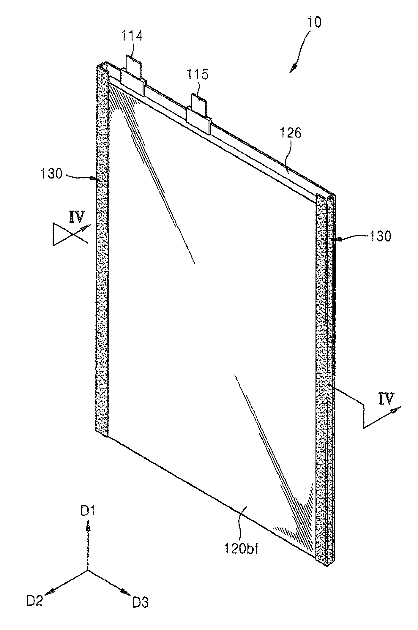
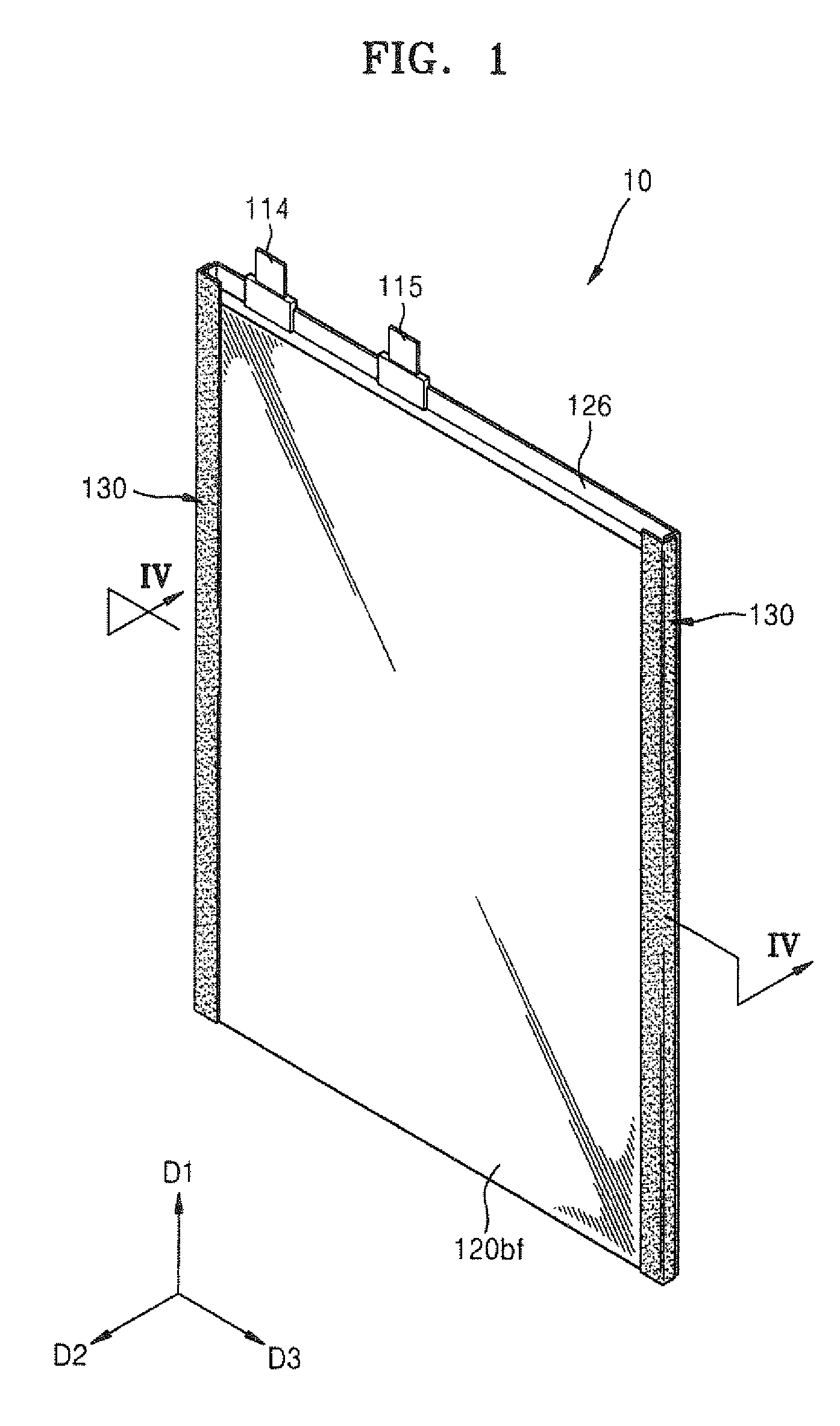
[0049]Case 120 may be constructed from an upper portion 120a forming a back surface 120ab of case and being located opposite to, and matingly engaging a lower portion 120b forming a front surface 120bf of case 120, and a first wing portion 124a located opposite to a second wing portion 124b, with each of the first and second wing portions corresponding in position to the seams where edges of the front portion are sealed to the back portion. Each of the upper and lower portions may be constructed from a metal layer arranged between an electrical insulating layer and a thermal bonding layer, with an electrical insulating film being adhered to and covering each of the wing portions along the lengths of the seam created at junctions formed by corresponding wing portions 124 and the front surface 120bf of case 120. In one exemplary design, the secondary battery may be constructed with an electrode assembly, a case that receivingly accommodates the insertion of the electrode assembly, the...

second embodiment

[0075]Turning now to FIG. 12, FIG. 12 is an oblique view illustrating a battery cell 20 according to the present invention. Referring to FIG. 12, the battery cell 20 includes the electrode assembly 110, the case 120, and insulating films 130′. A first portion 131′ of each of the insulating films 130′ are adhering to each of the wing portions 124 and a second portion 132′ are adhering to the front surface 120bf as described above with reference to FIGS. 1 through 4.

[0076]However, there is a difference between the battery cell 10 of FIG. 1 and the battery cell 20 of FIG. 12 in that through-holes 132h′ are formed in the insulating films 130′ that cover the wing portions 124 formed on both sides of the battery cell 20. The following explanation will focus on this difference.

[0077]Turning now to FIGS. 13A and 13B, FIGS. 13A and 13B are respectively an oblique view and an exploded oblique view of each of the insulating film 130′ / backing paper 140′ combination prior to use. Referring to FI...

first embodiment

[0080]A size of the backing paper 140′ may be greater than a size of the insulating film 130′ and may also be less than the size of the backing paper 140 of FIGS. 7A and 7B. While through-holes 142h are formed only in the second backing paper 142 in FIGS. 7A and 7B, through-holes 132h′ and 142h′ are formed in both the second portion 132′ of the insulating film 130′ and in the second backing paper 142′ in FIGS. 13A and 13B.

[0081]A process of attaching the insulating films 130′ of FIGS. 13A and 13B to the bare cell B by using the jig will now be explained with reference to FIGS. 14 through 16. The jig of FIGS. 14 through 16 is the same as the jig of FIGS. 5 through 9.

[0082]Referring now to FIG. 14, FIG. 14 is an oblique view illustrating a state where the insulating film 130′ and the bare cell B are mounted on the jig. As illustrated in FIG. 14, the battery cell 20 is mounted in the mount space R of the cell mount 40 such that the first wing portion 124a is disposed adjacent to and is...


PUM

PropertyMeasurementUnit
Lengthaaaaaaaaaa
Heightaaaaaaaaaa
aaaaaaaaaa

Abstract

A secondary battery, a jig suitable for fabrication of the secondary battery, and a method for producing a secondary battery constructed with a case accommodating the electrode assembly. The case includes a front portion terminated along opposite edges by a first wing portion and a second wing portion, and a back portion positioned opposite to the front portion, with insulating film bent along a length of a junction between the front portion and each of the first wing portion and the second wing portion, a pair of holes in the insulating film are held in parallel alignment with respect to the length of the junction, with the insulating film adhering to and covering the front portion and a corresponding one of the first wing portion and the second wing portion, in order to prevent leakage of electrolyte, and resulting corrosion of the electrically conducting metal components of the secondary battery.

Description

CLAIM OF PRIORITY[0001]This application makes reference to, incorporates the same herein, and claims all benefits accruing under 35 U.S.C. §119 from an application earlier filed in the U.S. Patent and Trademark Office on 29 Jul. 2011 and there duly assigned Ser. No. 61 / 513,350.BACKGROUND OF THE INVENTION[0002]1. Field of the Invention[0003]One or more embodiments of the present invention relate to an insulating film attaching jig and a battery cell manufactured by using the same.[0004]2. Description of Related Art[0005]In general, secondary batteries, which are rechargeable batteries unlike non-rechargeable primary batteries, are widely used in small high-tech electronic devices such as mobile phones, personal digital assistants (PDAs), and laptop computers.[0006]Among the various types of secondary batteries, a pouch-type secondary battery, which receives and seals an electrode assembly in a soft pouch-shaped case, provides a higher battery capacity than does an angular or a cylind...

Claims


Application Information

Patent Timeline
IPC IPC(8): H01M2/06B23P19/10B25B11/02H01M2/02H01M50/178H01M50/55H01M50/557
CPCY10T29/53265Y10T29/53135Y10T29/4911Y10T29/53191H01M2/0212H01M2/021Y02E60/10H01M50/557Y02P70/50H01M50/178H01M50/55H01M50/20H01M50/10H01M10/04
Inventor HONG, SUNG-HO
Owner SAMSUNG SDI CO LTD
Why Eureka
Try Eureka