Pool cleaner with brush

Inactive Publication Date: 2013-02-07
PORAT JOSEPH +1
View PDF7 Cites 41 Cited by
  • Summary
  • Abstract
  • Description
  • Claims
  • Application Information

AI Technical Summary

Benefits of technology

[0011]It is an object of embodiments of the invention to provide a brush for a robotic pool cleaner that

Problems solved by technology

These cleaners operate on the principle of lifting debris from the floor of the pool by suction and typically can only remove loose particles.
Thus any dirt that is found on the pool walls, typically oil-bound or of a biological nature, is often firmly attached to the surface and thus cannot be removed by suction alone.
The rotating action of a typical cleaner's brushes is generally insufficient to remov

Method used


Image

  • Pool cleaner with brush
  • Pool cleaner with brush
  • Pool cleaner with brush

Examples


Embodiment Construction

[0035]In the following detailed description, numerous specific details are set forth in order to provide a thorough understanding of the invention. However, it will be understood by those of ordinary skill in the art that the invention may be practiced without these specific details. In other instances, well-known methods, procedures, components, modules, units and / or circuits have not been described in detail so as not to obscure the invention.

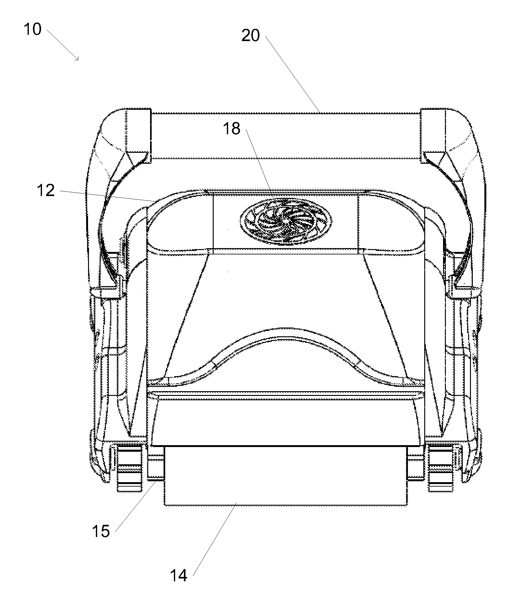
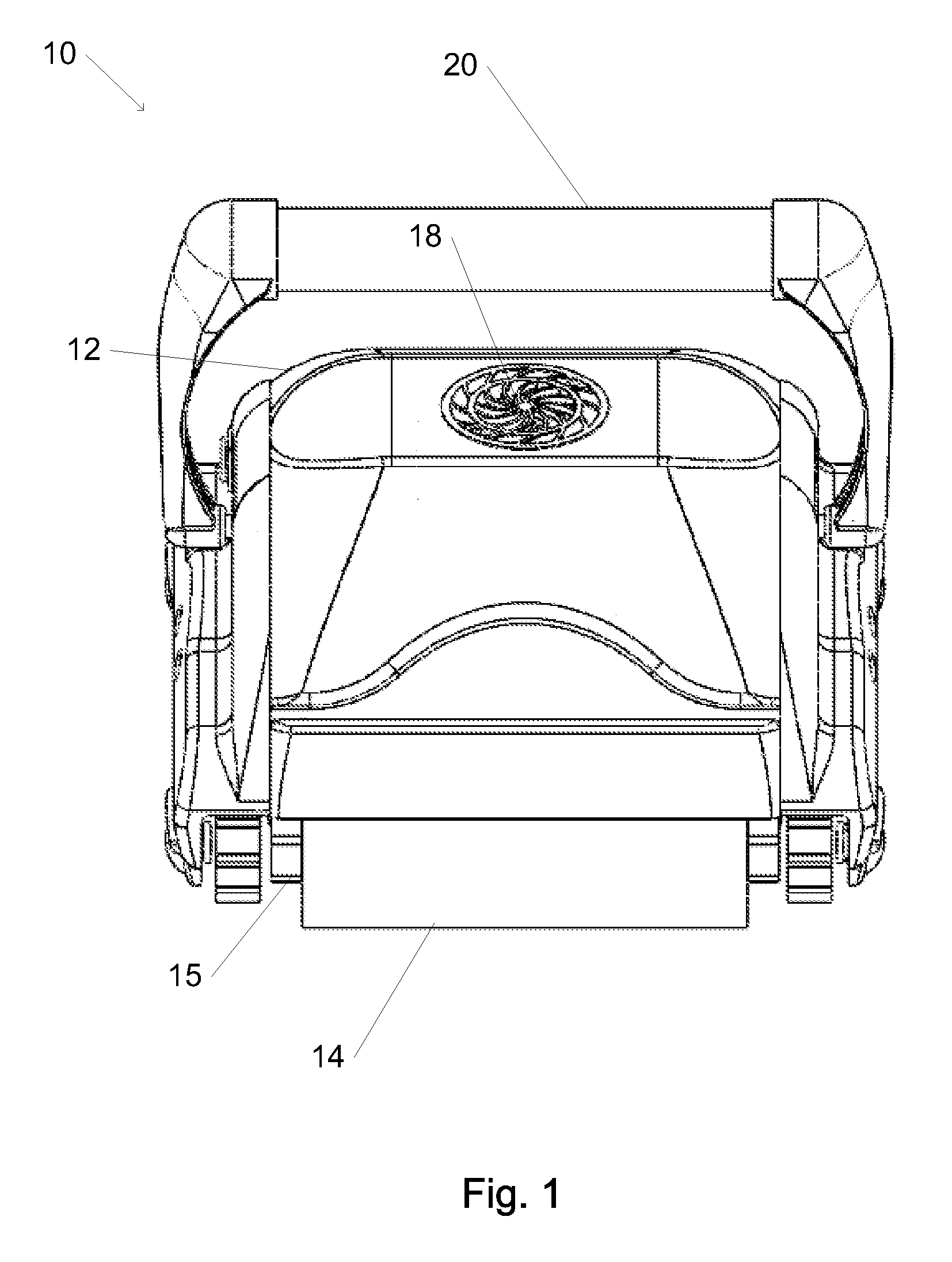
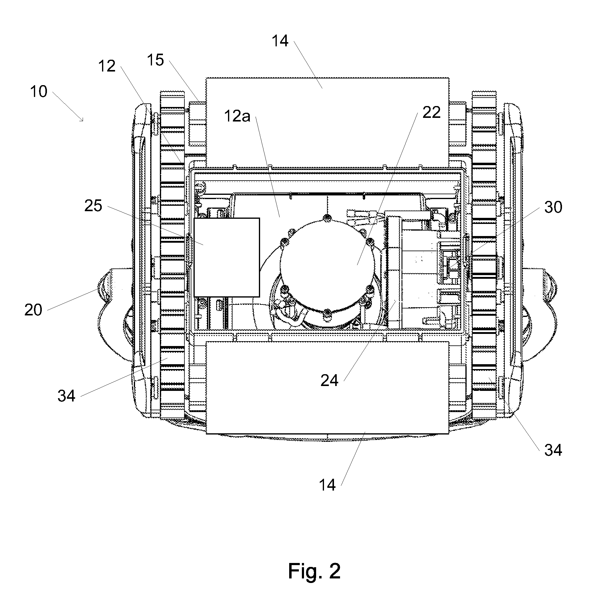
[0036]In accordance with an embodiment of the present invention, a pool cleaner is configured to travel along and clean an enclosing surface (e.g. a floor or wall) of a pool such as a swimming pool. For example, the pool cleaner may be an autonomously operating robotic pool cleaner. A front-rear axis of the pool cleaner is defined as an axis of the pool cleaner that is parallel to a nominal direction of motion of the pool cleaner (e.g. as determined by a direction of rolling of a wheel, roller, or track for propelling the pool cleaner along a...


PUM


Abstract

A pool cleaner device is configured to travel along an enclosing surface of a pool. The device includes at least one elongated brush having a long axis that is oriented at a nonzero angle to a lateral axis of the device and substantially parallel to the surface when the pool cleaner is traveling along the surface. The device also includes a mechanism for causing bristles of the elongated brush to vibrate against the surface when the device is operating on that surface.

Description

CROSS REFERENCE TO RELATED APPLICATIONS[0001]The present application claims priority from Israel application No. 214419 filed on Aug. 2, 2011, incorporated herein by reference in its entirety.FIELD OF THE INVENTION[0002]The present invention relates to pool cleaners. More particularly, the present invention relates to a pool cleaner with a brush.BACKGROUND OF THE INVENTION[0003]Swimming pools require frequent cleaning, often on a daily basis. Thus, autonomous devices for cleaning swimming pools often present an attractive alternative to manual cleaning. The use of electrically powered robotic swimming pool cleaners is a common method of cleaning dirt and debris from the bottom and sides of such pools.[0004]Robotic swimming pool cleaners have been described, for example, by Gard in US 2007 / 0028405. A robotic pool cleaner typically includes a drive motor and rollers, wheels, or tracks for locomotion. A robotic pool cleaner also typically includes a pump for drawing water through a fil...

Claims


Application Information

Patent Timeline
IPC IPC(8): E04H4/16
CPCE04H4/1654
Inventor PORAT, JOSEPHWEINBERG, YEHUDA
Owner PORAT JOSEPH
Why Eureka
Try Eureka