Membrane separation device for water treatment

A membrane separation and water treatment technology, applied in the field of water treatment, can solve the problems of shortening the service life of membrane modules, increasing the energy consumption of membrane separation equipment, and sludge accumulation of hollow fiber membranes, etc.

Active Publication Date: 2015-03-25
BEIJING ECOJOY WATER TECH +1
View PDF9 Cites 5 Cited by
  • Summary
  • Abstract
  • Description
  • Claims
  • Application Information

AI Technical Summary

Problems solved by technology

However, there is a common problem in the existing hollow fiber membrane modules: sludge accumulation at the root of the hollow fiber membrane is serious, and once the sludge is formed, it is not easy to remove, which reduces the effective area of ​​the membrane module and the uniformity of filtration. The continued development and spread of membrane fouling at the root of the filament will further aggravate the inhomogeneity of filtration and the loss of effective filtration area, and ultimately shorten the service life of the entire membrane module
Although increasing the aeration rate can alleviate the pollution of the hollow fiber membrane filament 01 to a certain extent, this measure not only significantly increases the operating energy consumption of the membrane separation equipment

Method used


Image

  • Membrane separation device for water treatment
  • Membrane separation device for water treatment
  • Membrane separation device for water treatment

Examples


Embodiment Construction

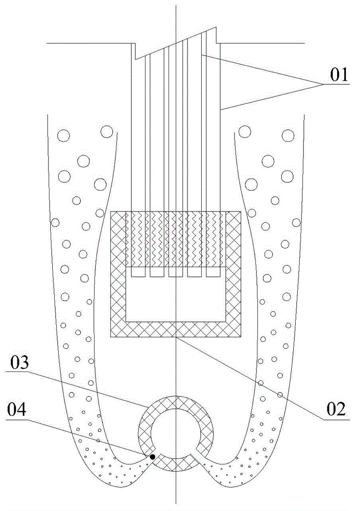
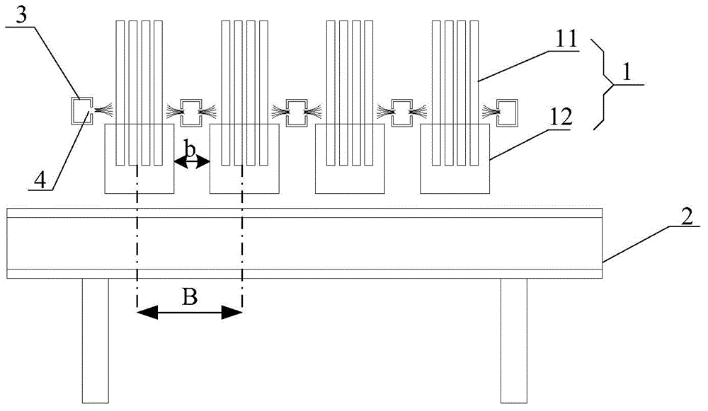
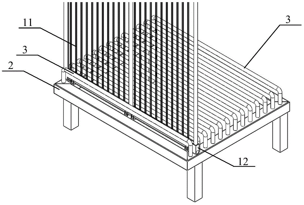
[0044] The core of the present invention is to provide a membrane separation device for water treatment, to effectively eliminate the problem of sludge accumulation at the root of the hollow fiber membrane, and to significantly improve the effective utilization rate of the hollow fiber membrane module inside the membrane separation device and the space of the entire membrane separation device Utilization, and reduce the operating energy consumption of membrane separation equipment.

[0045] The following will clearly and completely describe the technical solutions in the embodiments of the present invention with reference to the accompanying drawings in the embodiments of the present invention. Obviously, the described embodiments are only some, not all, embodiments of the present invention. Based on the embodiments of the present invention, all other embodiments obtained by persons of ordinary skill in the art without making creative efforts belong to the protection scope of t...


PUM


Abstract

The invention discloses a membrane separation device for water treatment. The device comprises hollow fiber curtain type membrane modules respectively provided with a lower end and a hollow fiber membrane bundle, a base used for supporting the lower ends, and a water collecting device communicated with water production holes of the hollow fiber curtain type membrane modules, wherein the hollow fiber membrane bundles are vertically arranged; a gap is reserved between every two adjacent hollow fiber curtain type membrane modules; an air distribution device provided with an air distribution hole is arranged between every two adjacent gaps; the air distribution devices are communicated with an aerating apparatus used for providing air flow; the air distribution holes are formed towards the roots of the hollow fiber membrane bundles, close to the lower ends. Each air distribution device is arranged between every two adjacent hollow fiber curtain type membrane modules, the mouths of the air distribution holes are formed towards the roots of the hollow fiber membrane bundles, the distances between the mouths of the air distribution holes and the roots of the membrane bundles are relatively short, and barriers do not exist between the mouths of the air distribution holes and the roots of the membrane bundles, so that the phenomenon of sludge deposition at the root of a membrane filament can be effectively avoided by relatively low aeration flow, the anti-pollution capacity of the membrane separation device can be improved, and the effective utilization rate of the membrane modules and the stability of the water-yielding capacity of the membrane separation device are remarkably improved.

Description

technical field [0001] The invention relates to the technical field of water treatment, and more specifically relates to a membrane separation device for water treatment. Background technique [0002] In recent years, due to the development of membrane science and technology and the upgrading of water treatment technology, membrane separation technology and membrane separation equipment using membrane separation technology are increasingly used in the field of water treatment. [0003] Among several membrane element forms such as flat membrane, tubular membrane and hollow fiber membrane, hollow fiber membrane has been widely used because of its high packing density and low cost. However, there is a common problem in the existing hollow fiber membrane modules: sludge accumulation at the root of the hollow fiber membrane is serious, and once the sludge is formed, it is not easy to remove, which reduces the effective area of ​​the membrane module and the uniformity of filtratio...

Claims


Application Information

Patent Timeline
IPC IPC(8): B01D63/02B01D61/00B01D65/08C02F1/44
Inventor 孙友峰钱珏
Owner BEIJING ECOJOY WATER TECH
Why Eureka
Try Eureka