Deposition method and apparatus

a technology of substrate and material, applied in the direction of positive displacement liquid engine, vanadium compound, pump, etc., can solve the problems of equipment deficiencies, insensitive to precursor transport non-uniformities, and insensitive to transport non-uniformities, and achieve high gas flow rates, low pressure, and rapid high pressure

Active Publication Date: 2011-03-24
SUNDEW TECH
View PDF18 Cites 4 Cited by
  • Summary
  • Abstract
  • Description
  • Claims
  • Application Information

AI Technical Summary

Benefits of technology

[0016]Based on these trends, one can see that conventional ALD clearly suffers from a fundamental tradeoff: injection and sweep sub-steps are made faster with lower pressures and higher gas flow rates while reaction sub-steps are made faster and less wasteful of precursor gases with higher pressures and lower gas flow rates. To overcome this tradeoff, process pressure and gas flow rates are preferably modulated in a synchronized manner with the different ALD sub-steps. Nevertheless, driving higher gas flow rates in many apparatus known in the art results in higher pressures so that any advantageous effects for ALD applications are lost. For example, the residence time τ=V×P / Q does not modulate when both pressure, P, and gas flow rate, Q, are modulated in phase with each other by roughly the same factor. Moreover, pressure / gas-flow-rate modulation techniques known in the art tend to employ relatively slow mechanical devices that modulate conductance (e.g., throttle valves) or devices that modulate pumping speed (e.g., devices that change the speed at which a component of the pump moves or rotates). These devices are not practical for the sub-second execution of ALD. For efficient ALD, the time required to modulate pressure and gas flow rates should not ideally exceed 10% of the process cycle time. For example, 100 milliseconds (ms) out of a one second cycle time leaves only about 25 ms for each pressure / gas-flow-rate transition (there are four such transitions per process cycle). Excluding other drawbacks, a transition time of about 25 ms is at least 100 times faster than the speed of most mechanical and pump speed modulation methodologies.
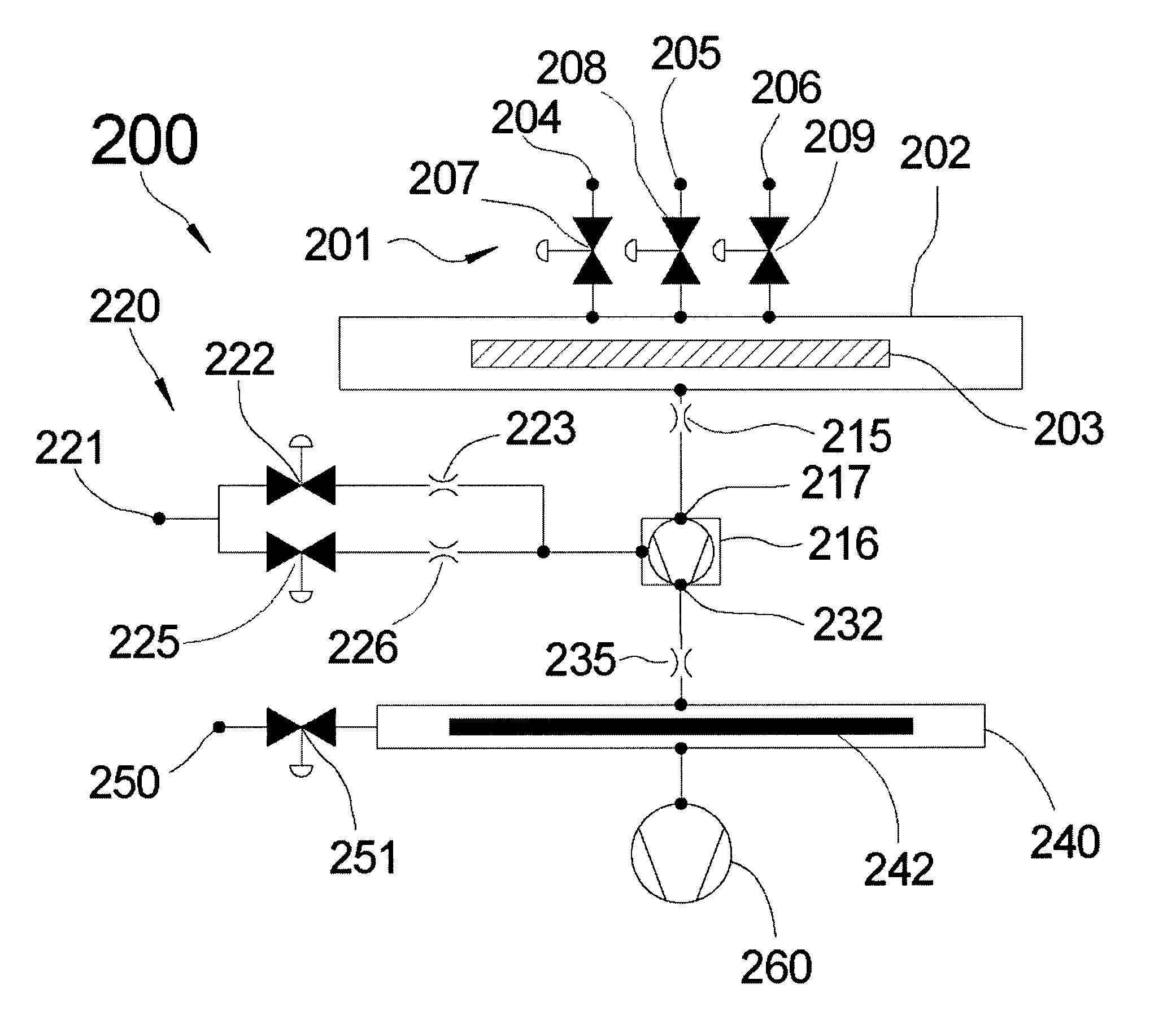
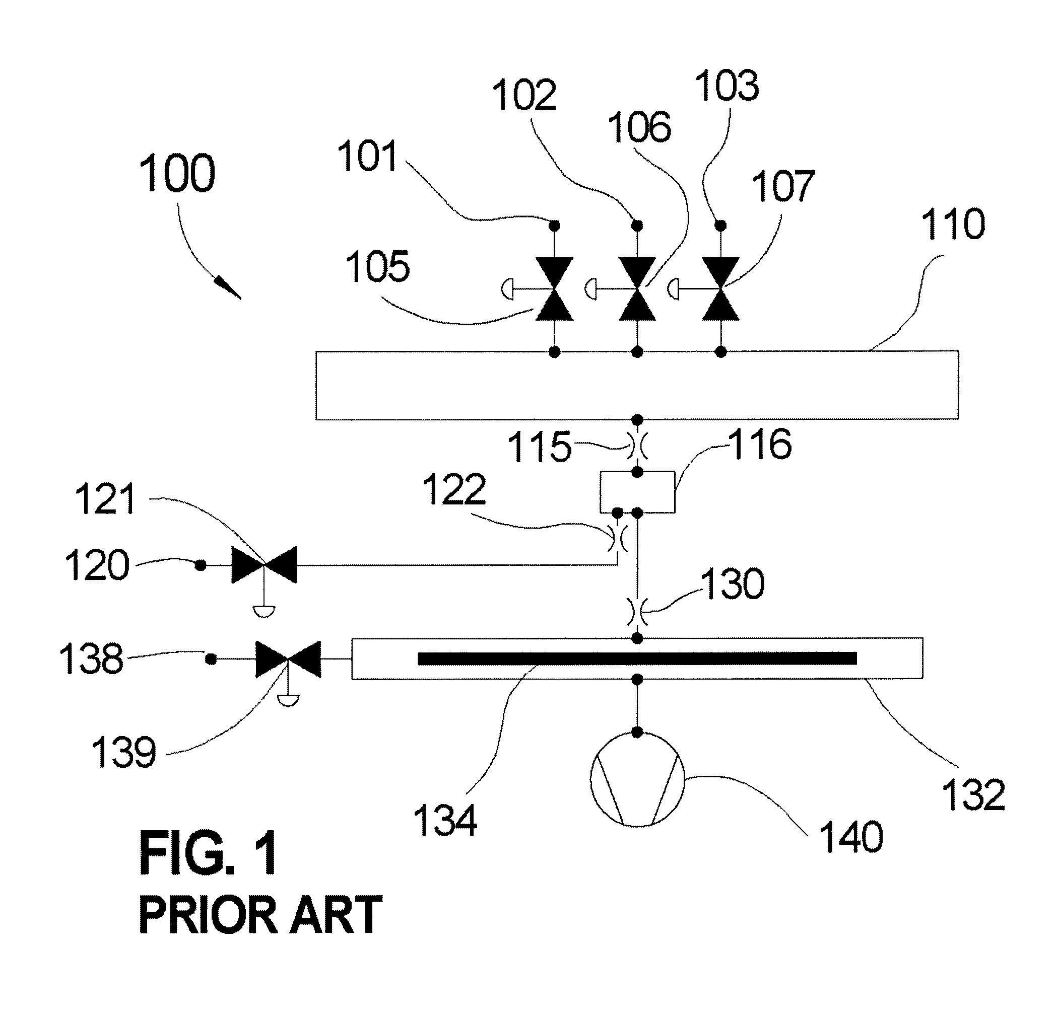
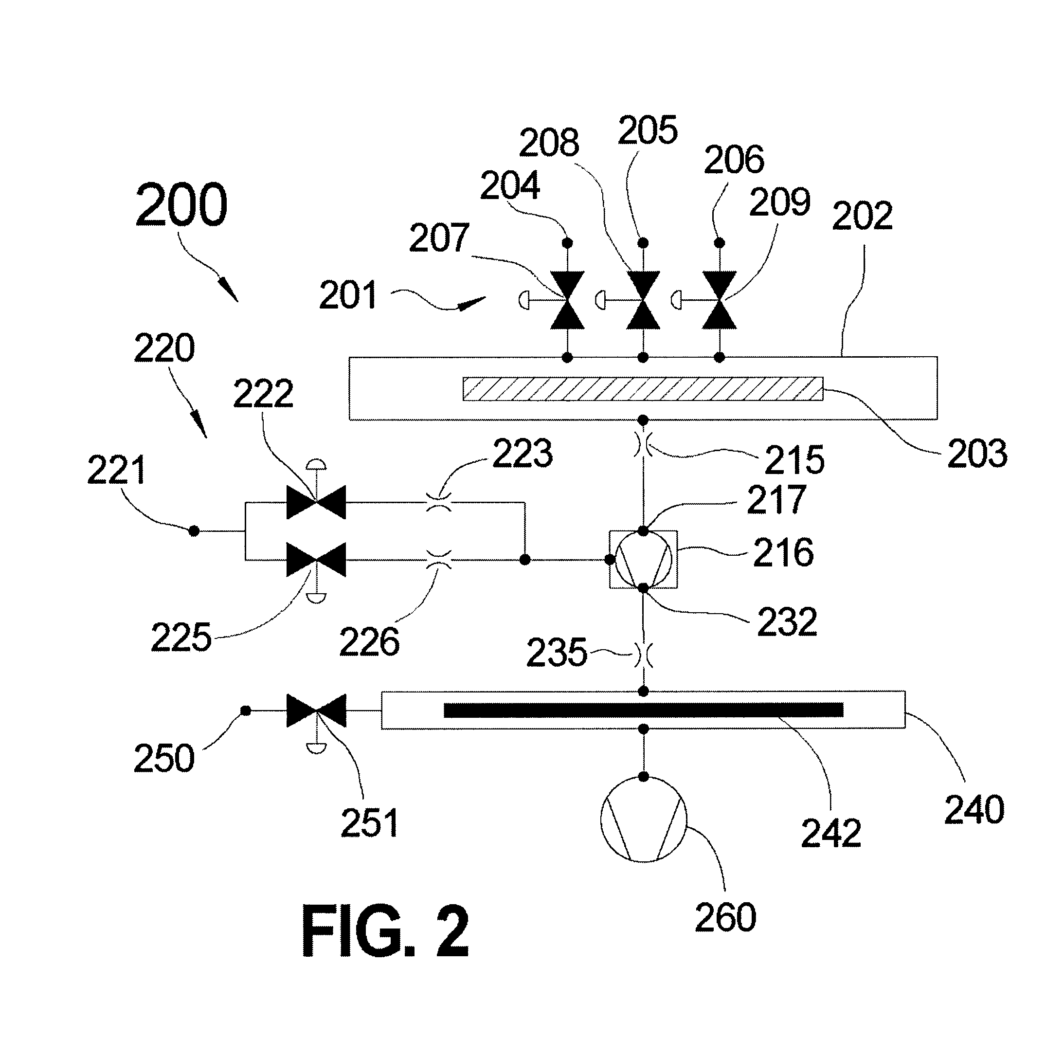
[0017]A novel ALD apparatus and method were taught by the inventor of the present invention in U.S. Pat. No. 6,911,092, entitled “ALD Apparatus and Method,” commonly assigned herewith and incorporated by reference herein. Aspects of this invention are shown in the schematic diagram shown in FIG. 1. As indicated in the figure, a “Synchronously Modulated Flow Draw” (SMFD) ALD system 100 comprises a first precursor gas source 101, a sweep gas source 102, and a second precursor gas source 103. These sources are plumbed into a first precursor gas valve 105, a sweep gas valve 106, and a second precursor gas valve 107, respectively, which control the flow of these process gases into inlets of a process space 110. Further downstream, a process space flow restriction element (FRE) 115 is attached to an outlet of the process space and carries gas drawn out of the process space into a small-volume draw gas introduction chamber (DGIC) 116. A draw gas source 120 is connected to the DGIC through a draw gas valve 121 and a draw gas FRE 122. Any gases drawn out of the DGIC enter a DGIC FRE 130 and then an abatement space 132, which contains an abatement surface 134. The abatement space is connected to an abatement gas source 138 and an abatement gas valve 139. The system is pumped by a vacuum pump 140.
[0018]The SMFD ALD system 100 is adapted to run process cycles comprising the six sub-steps described above. During sweep sub-steps, the draw gas valve 121 is closed and no draw gas is allowed to enter the DGIC 116. This, in turn, allows sweep gases injected into the process space to achieve relatively low pressures and relatively high gas flow rates. In contrast, during injection and reactions sub-steps, the draw gas valve is opened and draw gas is injected into the DGIC, allowing precursor gases injected into the process space to rapidly achieve relatively high pressures while accommodating relatively low gas flow rates. More particularly, given the small volume of DGIC and the high flow of the draw gas, a substantial pressure gradient quickly develops over the DGIC FRE 130 when draw gas is injected into the DGIC. As a result, pressure in the DGIC quickly increases and the pressure gradient over the process space FRE 115, ΔPDraw, quickly decreases. In this manner, the gas flow rate out of the process space is modulated by effectively modulating ΔPDraw. If the DGIC has a small volume, very fast transition speeds may be obtained. For example, a DGIC having a volume of about 75 cubic centimeters (cm3) implemented within a commercially available SMFD ALD system designed to deposit materials on eight inch wafer-sized substrates is capable of less than 5 ms transition times.
[0019]For gas abatement purposes, an abatement gas from the abatement source 138 is introduced through the abatement gas valve 139 into the abatement space 132 during sweep sub-steps to drive an efficient reaction with any precursor gases that may have passed through the process space 110 without being reacted. The products of this abatement reaction deposit as a solid film on the abatement surface 134, thereby effectively scrubbing the leftover precursor gas waste from the exhaust effluent. Advantageously, the high gas flow rate through the DGIC 116 effectively separates the abatement space from the process space to allow flexible abatement gas selection without affecting the actual ALD process. Abatement accomplished in this manner has been shown to extend pump life significantly over that normally seen in conventional ALD systems.
[0020]Based on this brief description as well as the details provided in U.S. Pat. No. 6,911,092, it will be clear to one skilled in the art that SMFD ALD methods and apparatus provide several advantages with respect to productivity, efficiency, and cost over other ALD methods and apparatus known in the art. For this reason, it is desirable to further develop new methods and apparatus for implementation of SMFD-like ALD which may provide even greater advantages and capabilities.SUMMARY OF THE INVENTION
[0021]Embodiments of the present invention address the above-identified need by providing methods and apparatus for depositing materials on substrates by ALD utilizing Gaede pump stages (GPSs) to modulate the pressures and gas flow rates of precursor gases and sweep gases.

Problems solved by technology

Moreover, self-saturating surface reactions make ALD insensitive to precursor transport non-uniformities (i.e., spatial non-uniformity in the rate that the precursor gases impinge on the substrate) that often plague other deposition techniques like chemical vapor deposition and physical vapor deposition.
Transport non-uniformities may result from equipment deficiencies or may be driven by substrate topography.
Nonetheless, in the case of self-saturating ALD reactions, if each of the reaction sub-steps is allowed to self-saturate across the entire substrate surface, transport non-uniformities become irrelevant to film growth rate.
In addition to cycle time, productivity is also affected by equipment uptime (i.e., the fraction of the time that the equipment is up and running properly), cost of consumables (e.g., precursor gases, sweep gases), cost of maintenance, power, overhead (e.g., floor space), and labor.
At these lower temperatures, reaction rates are relatively slow or only moderate in speed.
Instead, higher gas flow rates will only result in extensive precursor waste.
Since many of the precursor gases used in ALD are extremely reactive, un-reacted precursor gas that is swept through the process space swiftly drives the equipment to malfunction or to fail.
Bearing in mind, however, that precursor waste and related equipment failure, downtime, and maintenance are perhaps the most dominant cost factors, best ALD practices generally dictate that injection sub-steps not be carried out beyond 35% volume exchange (e.g., about τi) under these gas flow rate conditions.
Otherwise, high concentration loading will result in excessive precursor waste during the injection sub-step.
Nevertheless, driving higher gas flow rates in many apparatus known in the art results in higher pressures so that any advantageous effects for ALD applications are lost.
Moreover, pressure / gas-flow-rate modulation techniques known in the art tend to employ relatively slow mechanical devices that modulate conductance (e.g., throttle valves) or devices that modulate pumping speed (e.g., devices that change the speed at which a component of the pump moves or rotates).
These devices are not practical for the sub-second execution of ALD.

Method used


Image

  • Deposition method and apparatus
  • Deposition method and apparatus
  • Deposition method and apparatus

Examples


Embodiment Construction

[0038]The present invention will be described with reference to illustrative embodiments. For this reason, numerous modifications can be made to these embodiments and the results will still come within the scope of the invention. No limitations with respect to the specific embodiments described herein are intended or should be inferred.

[0039]As used herein, the symbol Pxy shall refer to the pressure at location x during the sub-step y, where y=s for sweep sub-steps, y=i for injection sub-steps, and y=r for reaction sub-steps. Moreover, as used herein, a GPS is meant to encompass any apparatus operative to pump gas by means of a moving surface.

[0040]FIG. 2 shows a schematic diagram of an illustrative SMFCD ALD system 200 in accordance with an illustrative embodiment of the invention. The SMFCD ALD system comprises a process gas manifold 201 operative to introduce precursor gases and sweep gas into a process space 202 containing a substrate 203. The process gas manifold comprises a fi...


PUM

PropertyMeasurementUnit
residence timeaaaaaaaaaa
volumeaaaaaaaaaa
thickaaaaaaaaaa

Abstract

A method of depositing a material on a substrate comprises placing a substrate into a process space in fluidic communication with a Gaede pump stage (GPS). A precursor gas is then injected into the process space while injecting a draw gas at a draw gas flow rate into the GPS such that the injected precursor gas achieves a precursor pressure and a precursor gas flow rate in the process space. Subsequently, substantially all of the precursor gas remaining in the process space is swept from the process space by injecting a sweep gas into the process space such that the injected sweep gas achieves a sweep pressure and sweep gas flow rate in the process space. The precursor pressure is higher than the sweep pressure, and the precursor gas flow rate is lower than the sweep gas flow rate.

Description

FIELD OF THE INVENTION[0001]The present invention relates generally to methods and apparatus for depositing materials on substrates, and, more particularly, to methods and apparatus for depositing materials on substrates using atomic layer deposition with modulated pressures and gas flow rates.BACKGROUND OF THE INVENTION[0002]Atomic layer deposition (ALD) provides highly conformal material coatings with exceptional quality, atomic layer control, and uniformity. Coatings deposited by ALD are, for example, well suited for protecting many products from corrosion and harsh ambient conditions. Effective corrosion protective ALD coatings may only be about 200 to about 1,000 nanometers (nm) thick, making them thin enough not to impact the dimensions or the bulk properties of most of the parts and products on which they are deposited. Moreover, ALD coatings typically display excellent conformality and hermetic sealing properties. As a result, potential applications for ALD coatings are wide...

Claims


Application Information

Patent Timeline
Patent Type & Authority Applications(United States)
IPC IPC(8): C01B15/14C01B33/20C01B33/00C01C1/28C01G41/02C01F7/02C01G35/00C23C16/448F04B35/00
CPCC23C16/45544F04D25/0666C23C16/45502
Inventor SNEH, OFER
Owner SUNDEW TECH
Why Eureka
Try Eureka