
Transmission x-ray analyzer and transmission x-ray analysis method

a technology of transmission x-ray and analyzer, which is applied in the direction of material analysis using wave/particle radiation, optical radiation measurement, instruments, etc., can solve the problems of difficult adjustment of the number of integration stages of the measurer, and the inability to grasp the entire sample, so as to achieve the effect of easy adjustment of the number of integration stages of the tdi sensor

Active Publication Date: 2013-02-07
HITACHI HIGH TECH SCI CORP
View PDF5 Cites 9 Cited by
  • Summary
  • Abstract
  • Description
  • Claims
  • Application Information

AI Technical Summary

Benefits of technology

The present invention provides an X-ray analyzer and an X-ray analysis method that can easily adjust the number of integration stages of a TDI sensor in a wide range. This is achieved through the use of a shield means, which allows for physical adjustment of the sensor's number of integration stages, reducing the need for a dedicated sensor and lowering costs. Additionally, the invention allows for adjustment of the sensor's movement amount, resulting in greater flexibility in the depth of field and allowing for a larger range of thick samples to be focused. Overall, the invention provides a more efficient and flexible means of X-ray analysis.

Problems solved by technology

Further, in the case of adjusting the number of integration stages through use of a dedicated TDI sensor, it is difficult for a measurer to freely adjust the number of integration stages.
Therefore, the entire sample may not be grasped.

Method used


Image

  • Transmission x-ray analyzer and transmission x-ray analysis method
  • Transmission x-ray analyzer and transmission x-ray analysis method
  • Transmission x-ray analyzer and transmission x-ray analysis method

Examples


Embodiment Construction

[0022]Hereinafter, an embodiment of the present invention is described with reference to the drawings.

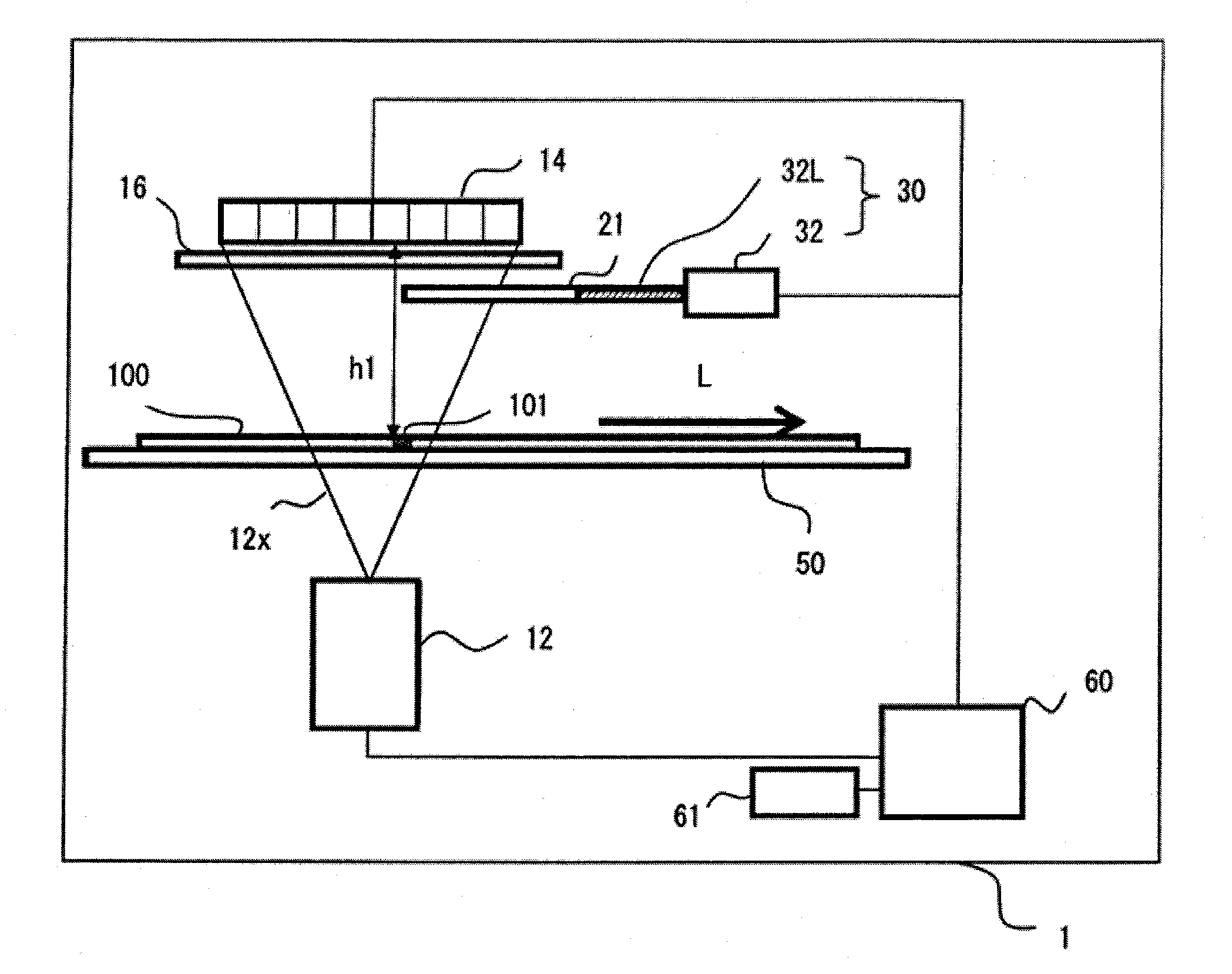
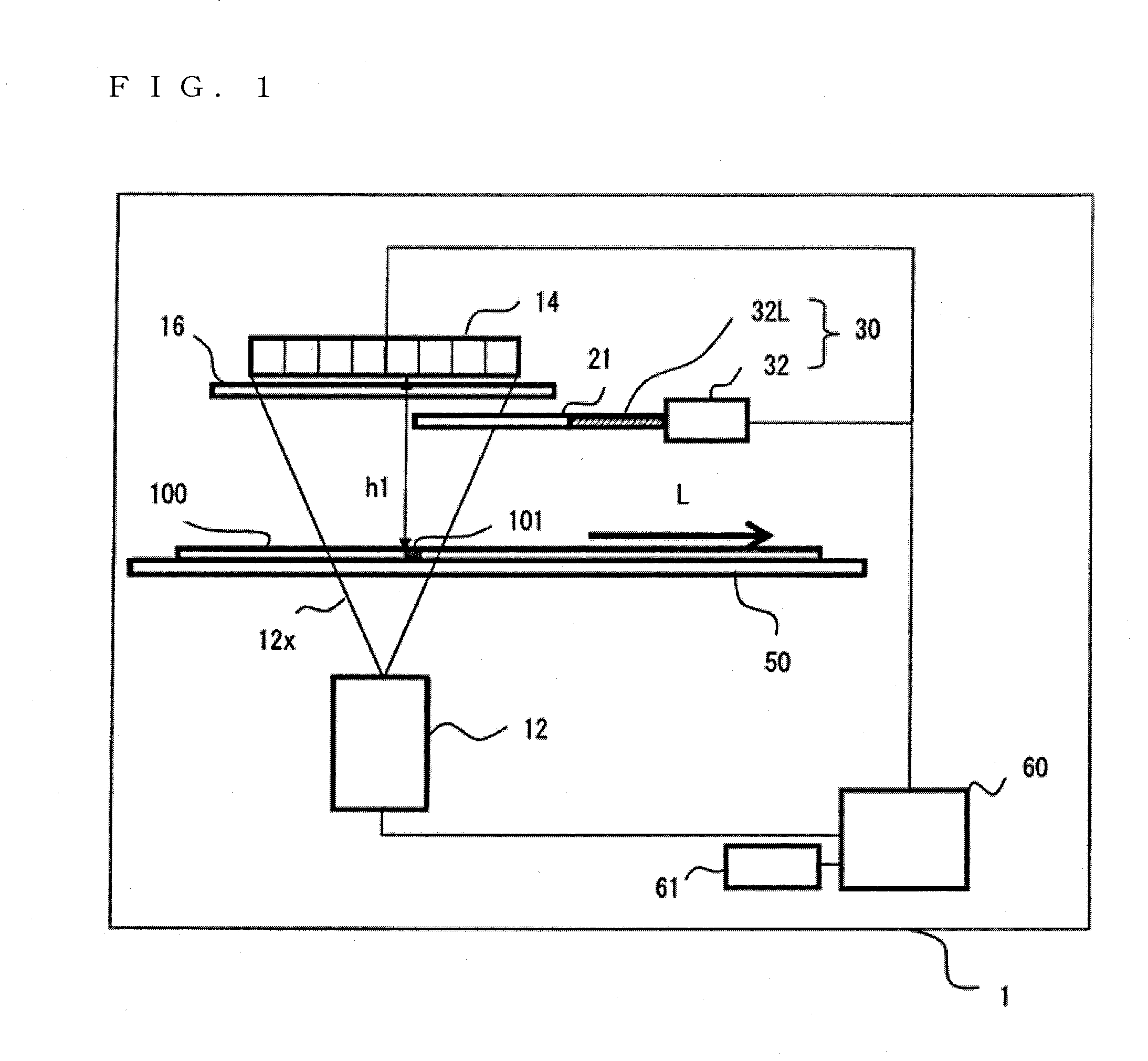
[0023]FIG. 1 is a block diagram illustrating a configuration of a transmission X-ray analyzer 1 according to the embodiment of the present invention.

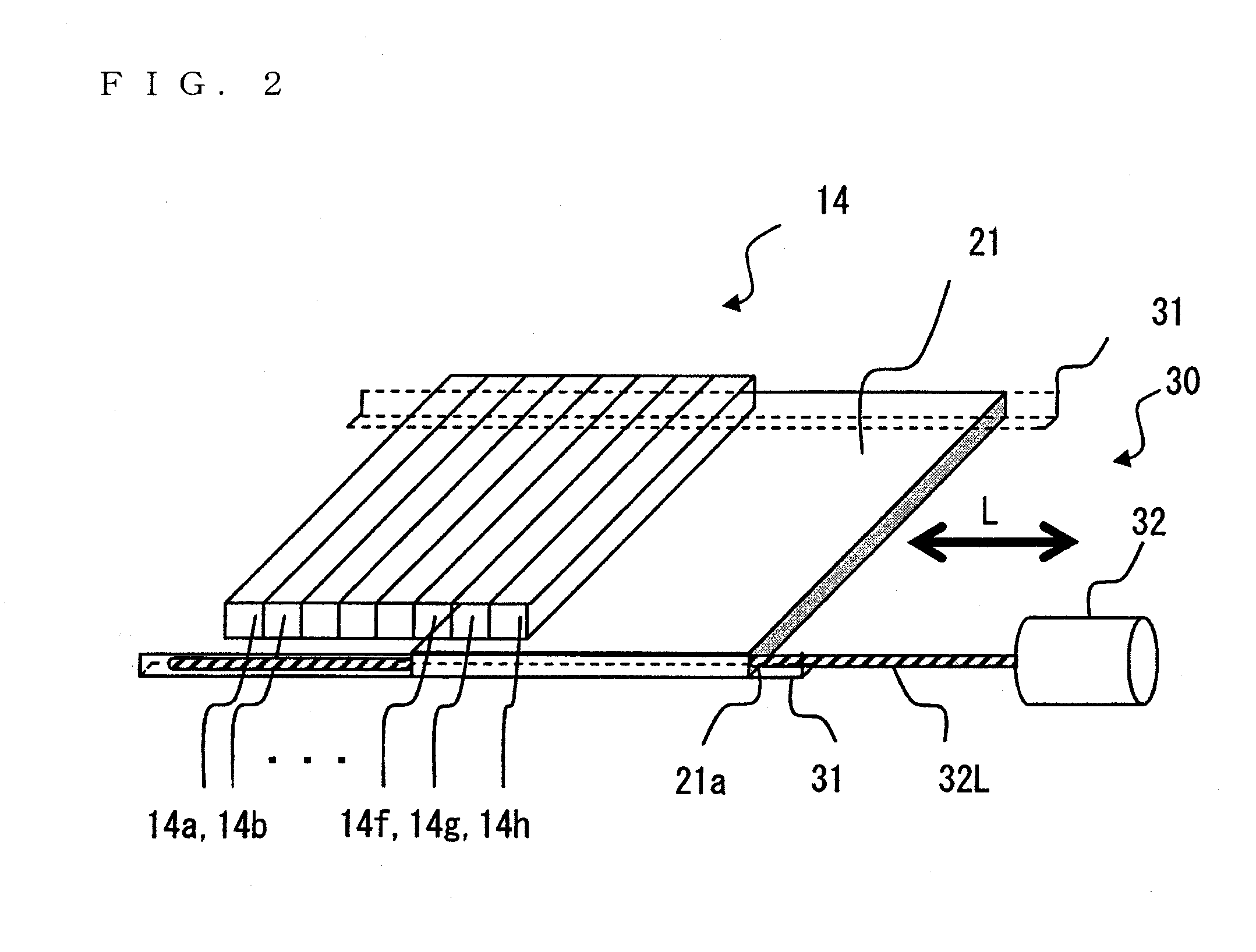
[0024]The transmission X-ray analyzer 1 includes: an X-ray source 12; a time delay and integration (TDI) sensor 14; a fluorescent screen 16 that is disposed between the TDI sensor 14 and a sample 100 and configured to convert a transmission X-ray 12x from the sample 100 into fluorescent light (visible light image); a shield plate (shield means) 21 that is disposed below the fluorescent screen 16 and configured to shield a part of an image of visible light entering the TDI sensor 14; shield plate movement means 30 for moving the shield plate 21 back and forth relative to the TDI sensor 14; and shield means position control means 60 for controlling the position of the shield plate 21.

[0025]Herein, the X-ray source 12 is disposed below the...


PUM


Abstract

A transmission X-ray analyzer for detecting a transmission X-ray image of a sample that moves relatively in a predetermined scanning direction includes; a time delay and integration (TDI) sensor including a plurality of stages of line sensors including the plurality of two-dimensionally arranged image pickup devices arranged in a direction perpendicular to the predetermined scanning direction, being configured to transfer charge accumulated in one line sensor to an adjacent subsequent line sensor; a shield unit for shielding a part of the image of light entering the TDI sensor by moving back and forth in the predetermined scanning direction, the shield unit being disposed between the TDI sensor and the sample; and a shield unit position control unit for controlling a position of the shield unit so as to shield a predetermined number of stages of line sensors among the plurality of stages of line sensors.

Description

BACKGROUND OF THE INVENTION[0001]1. Field of the Invention[0002]The present invention relates to a transmission X-ray analyzer and a transmission X-ray analysis method, which are capable of measuring a transmission X-ray output from a sample through use of a time delay and integration (TDI) sensor.[0003]2. Description of the Related Art[0004]Conventionally, a foreign matter in a sample and density unevenness of elements have been detected by X-ray transmission imaging. As a method of the X-ray transmission imaging, there is known a method of converting a transmission X-ray output from a sample into fluorescent light through a fluorescent screen or the like, and detecting the fluorescent light through use of image pickup devices (charge coupled devices (CCDs)). As a detection method using CCDs, there is a method of scanning a sample to obtain linear images successively through use of a line sensor having a plurality of image pickup devices arranged in one direction, thereby obtaining...

Claims


Application Information

Patent Timeline
Patent Type & Authority Applications(United States)
IPC IPC(8): G01T1/17
CPCG01N2223/3307G01N23/083
Inventor MATOBA, YOSHIKI
Owner HITACHI HIGH TECH SCI CORP
Learn More