Backlight device and liquid crystal display apparatus

a liquid crystal display and backlight technology, applied in lighting and heating apparatus, planar/plate-like light guides, instruments, etc., can solve the problems of increasing the amount of unwanted light, affecting the color reproduction range, and affecting the use efficiency of light by the liquid crystal display element, so as to achieve the effect of reducing power consumption and expanding the color reproduction rang

Inactive Publication Date: 2013-02-07
MITSUBISHI ELECTRIC CORP
View PDF5 Cites 50 Cited by
  • Summary
  • Abstract
  • Description
  • Claims
  • Application Information

AI Technical Summary

Benefits of technology

[0026]The backlight device and liquid crystal display apparatus according to the present invention ca...

Problems solved by technology

Narrowing the wavelength of light that passes through the color filters increases the amount of unwanted light.
In other words, usage efficiency of light by the liquid crystal display element deteriorates greatly.
Furthermore, if it is tried to improve the luminance, the power consumption of the liquid crystal display apparatus increases.
When the light rays emitted from these light sources are mixed to generate white light, however, a difference in spatial luminance distribution on the display surface of the liquid crystal display element of the different colors appea...

Method used


Image

  • Backlight device and liquid crystal display apparatus
  • Backlight device and liquid crystal display apparatus
  • Backlight device and liquid crystal display apparatus

Examples


first embodiment

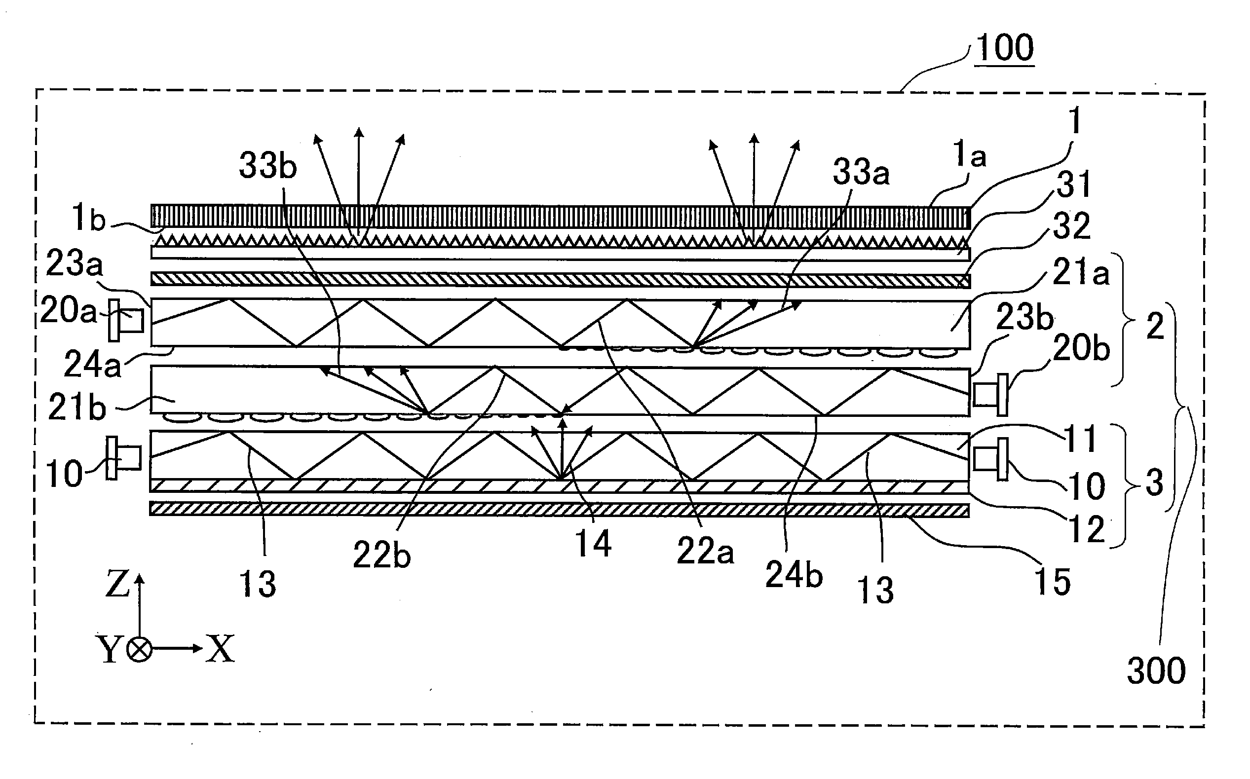
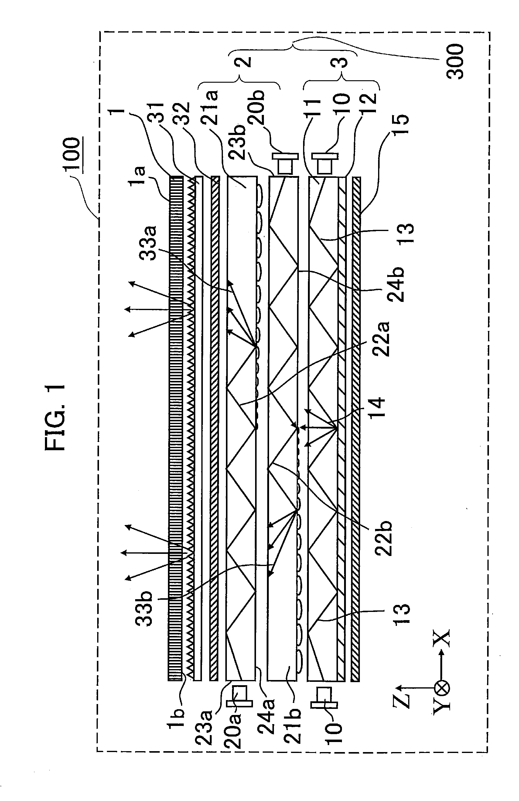
[0048]FIG. 1 is a diagram schematically showing structure of a liquid crystal display apparatus 100, which is a transmission-type display apparatus according to a first embodiment of the present invention. A backlight device in the first embodiment includes a first backlight unit 2 and a second backlight unit 3. For ease of understanding, let a short side direction of a liquid crystal optical element 1 be a Y-axis direction, a long side direction of the liquid crystal optical element 1 (direction orthogonal to a Y-axis) be an X-axis direction, and a direction perpendicular to an X-Y plane be a Z-axis direction. In addition, let a side of a display surface la of the liquid crystal display element 1 be a positive Z-axis direction, an upper direction of the liquid crystal display apparatus (an upper direction when the liquid crystal display apparatus 100 is placed so that its screen faces in a horizontal direction) be a positive Y-axis direction, and a light output direction of a first...

second embodiment

[0104]FIG. 7 is a diagram schematically showing structure of a liquid crystal display apparatus (transmission-type liquid crystal display apparatus) 600 according to a second embodiment of the present invention. A backlight device in the second embodiment includes a first backlight unit 2 and a second backlight unit 4. The liquid crystal display apparatus 600 in the second embodiment differs from the liquid crystal display apparatus 100 in the first embodiment in that the second backlight unit 3 of the liquid crystal display apparatus 100 of the first embodiment is replaced with the second backlight unit 4 having a different structure. Otherwise, the liquid crystal display apparatus 600 of the second embodiment is basically the same as the liquid crystal display apparatus 100 of the first embodiment. In FIG. 7, elements that are identical to or correspond to the elements of the liquid crystal display apparatus 100 described in the first embodiment (FIG. 1) are denoted by the same re...

third embodiment

[0108]FIG. 8 is a diagram schematically showing structure of a liquid crystal display apparatus (transmission-type liquid crystal display apparatus) 700 according to a third embodiment of the present invention. A backlight device in the third embodiment includes a first backlight unit 7 and a second backlight unit 3. The liquid crystal display apparatus 700 in the third embodiment is a more suitable form of the liquid crystal display apparatus 100 in the first embodiment. In the liquid crystal display apparatus 700 in the third embodiment, conditions of an optical transmission portion are studied in detail and improved. In FIG. 8, elements having functions identical to or corresponding to the elements used in the first embodiment (FIG. 1) are denoted by the same reference numerals. Elements that will be described in detail in the third embodiment are denoted by new reference numerals, separately from the elements of the first embodiment.

[0109]In the liquid crystal display apparatus ...


PUM


Abstract

A planar light source device includes a first light source for emitting a first light ray having a punctate spatial luminance distribution; a second light source for emitting a second light ray; a first spatial luminance distribution conversion portion for changing the first light ray to a linear spatial luminance distribution; a second spatial luminance distribution conversion portion for changing a spatial luminance distribution of the first and second light rays to a planar spatial luminance distribution; wherein the first light ray is a laser light; the second light ray has a divergence angle larger than the divergence angle of the first light ray when the first light ray is emitted from the first light source; and a slow-axis direction of the first light ray entering the second spatial luminance distribution conversion portion is parallel to an outgoing direction of the planar light.

Description

TECHNICAL FIELD[0001]The present invention relates to a backlight device using a laser light source to illuminate a liquid crystal display element from a back surface side of the liquid crystal display element and a liquid crystal display apparatus including the backlight device.BACKGROUND ART[0002]Since a liquid crystal display element included in a liquid crystal display apparatus does not emit light for itself, a backlight device must be provided on the back surface side of the liquid crystal display element as a light source for illuminating the liquid crystal display element. In recent years, demand for thinner liquid crystal display apparatuses has been rising. Sidelight-type backlight devices which include a thin plate-like light guide plate and a light source disposed so as to face a side of the light guide plate and create a planar light source by entering light from a side face of the light guide plate are widely used.[0003]The conventional mainstream of the light source o...

Claims


Application Information

Patent Timeline
IPC IPC(8): G02F1/13357F21V8/00G09F13/04
CPCG02B6/002G02B6/003G02B6/0036G02B6/0061G02F2001/133614G02B6/0076G02F1/133603G02F1/133615G02F1/133621G02B6/0068G02F1/133624G02F1/133614
Inventor NISHITANI, RENASASAGAWA, TOMOHIRONIIKURA, EIJIKOJIMA, KUNIKOSOMEYA, JUNSUGIURA, HIROAKITSUTSUMI, KAZUHIKONAGASE, AKIHIRO
Owner MITSUBISHI ELECTRIC CORP
Why Eureka
Try Eureka