Soil compaction device having a disconnectable fuel line
a soil compaction device and fuel line technology, applied in the direction of liquid fuel feeders, engine diaphragms, soil preservation, etc., can solve the problems of unfavorable fuel flow interruption and increase the operational reliability of soil compaction devices, and achieve the effect of high operational reliability
- Summary
- Abstract
- Description
- Claims
- Application Information
AI Technical Summary
Benefits of technology
Problems solved by technology
Method used
Image
Examples
first embodiment
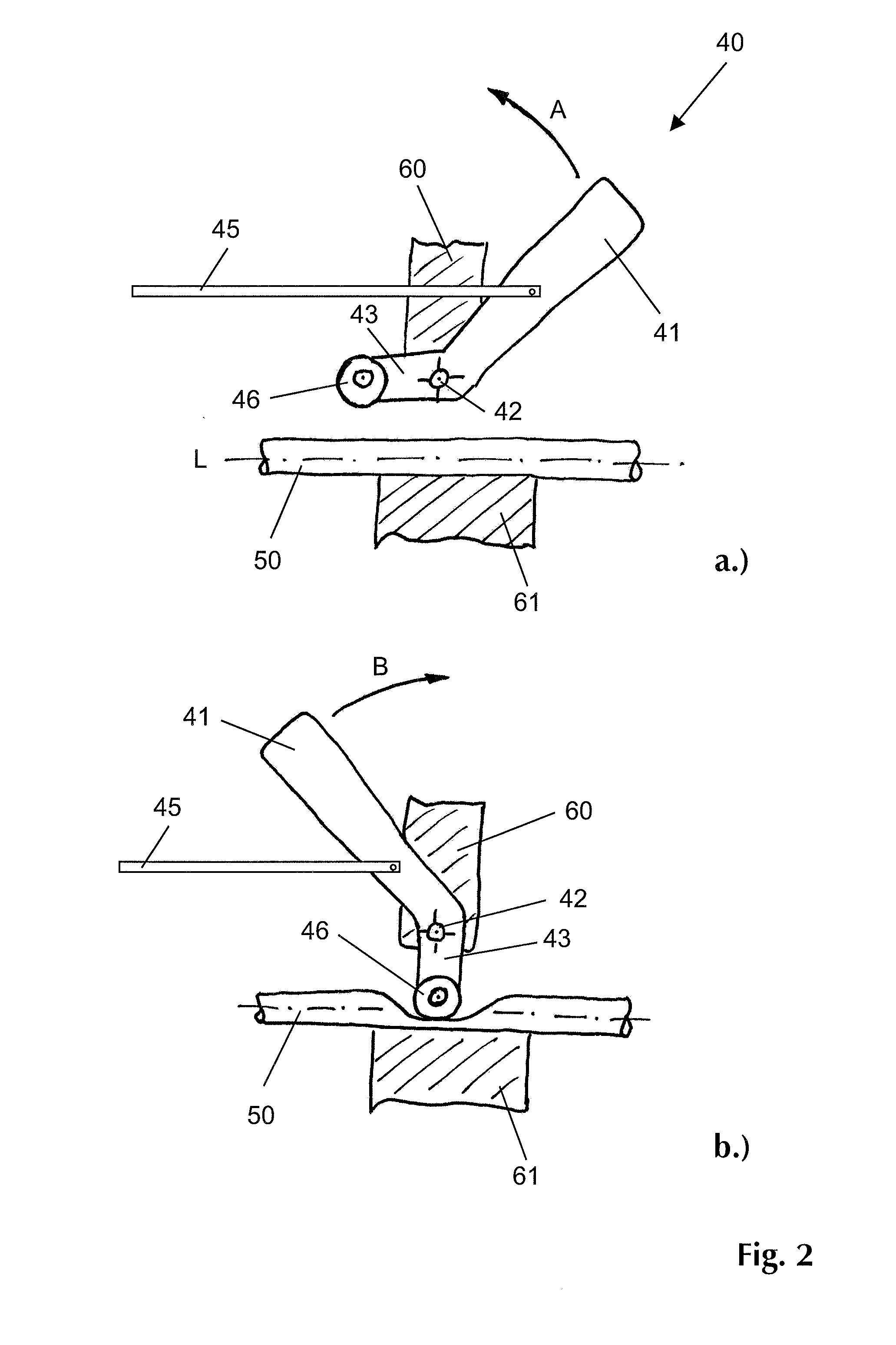
[0026]FIG. 3 shows another embodiment of the present invention. The same components and / or components with the same function are designated with the same reference numerals. The illustrations show the same actuating lever 41 in a first operating position (FIG. 3a), in a second operating position or idle or start position (FIG. 3b), and in a stop position (FIG. 3c). Only the relevant differences compared to FIG. 2, will be described below.
[0027]Deviating from the first embodiment of FIG. 2, the actuating lever 41 is provided with an eccentric cam 44 which in the stop position (FIG. 3c) presses the flexibly elastic section 50 of the fuel line against the rigid clamping jaw 61 by means of a movable pressure element or clamping element 70, by means of which the fuel flow through the fuel line is disconnected. The movable pressure element 70 transmits the clamping force applied by the cam 44 and simultaneously absorbs the frictional and / or thrust forces resulting from the relative moveme...
second embodiment
[0028]FIG. 4 shows a further embodiment of the present invention. The same components and / or components with the same function are designated with the same reference numerals. The illustration shows the actuating lever 41 in a first operating position which corresponds to the operating position as shown in FIG. 3a. Only the relevant differences compared to FIG. 3, will be described below.
[0029]Deviating from the second embodiment of FIG. 3, two line sections 50 and 51 are arranged between the movable pressure element 70 and the clamping jaw 61. The section 50 concerns a section of the fuel line which connects the tank container 32 with the internal combustion engine 31, as already described above. The section 51 concerns the section of a vent line which is used for venting and / or airing the tank container 32. Both line sections 50 and 51 are simultaneously clamped by means of the cam 44 and the movable clamping element 70 when the actuating lever 41 is moved from the illustrated ope...
PUM
 Abstract
Description
Claims
Application Information
 - R&D
- Intellectual Property
- Life Sciences
- Materials
- Tech Scout
- Unparalleled Data Quality
- Higher Quality Content
- 60% Fewer Hallucinations
Browse by: Latest US Patents, China's latest patents, Technical Efficacy Thesaurus, Application Domain, Technology Topic, Popular Technical Reports.
© 2025 PatSnap. All rights reserved.Legal|Privacy policy|Modern Slavery Act Transparency Statement|Sitemap|About US| Contact US: help@patsnap.com


