Optical element, and optical system and optical apparatus using same

a technology of optical elements and optical systems, applied in the direction of thin material handling, instruments, coatings, etc., can solve the problems of unsatisfactory increase in refractive index, and achieve the effects of low refractive index, excellent scratch resistance, and high anti-reflection performan

Active Publication Date: 2013-02-07
CANON KK
View PDF5 Cites 11 Cited by
  • Summary
  • Abstract
  • Description
  • Claims
  • Application Information

AI Technical Summary

Benefits of technology

[0006]Accordingly, the present invention provides an optical element that exhibits excellent scratch resistance and high anti-reflection performance while ensuring a low refractive index.

Problems solved by technology

However, a highly-filled binder may cause an undesirable increase in refractive index.

Method used


Image

  • Optical element, and optical system and optical apparatus using same
  • Optical element, and optical system and optical apparatus using same
  • Optical element, and optical system and optical apparatus using same

Examples


first embodiment

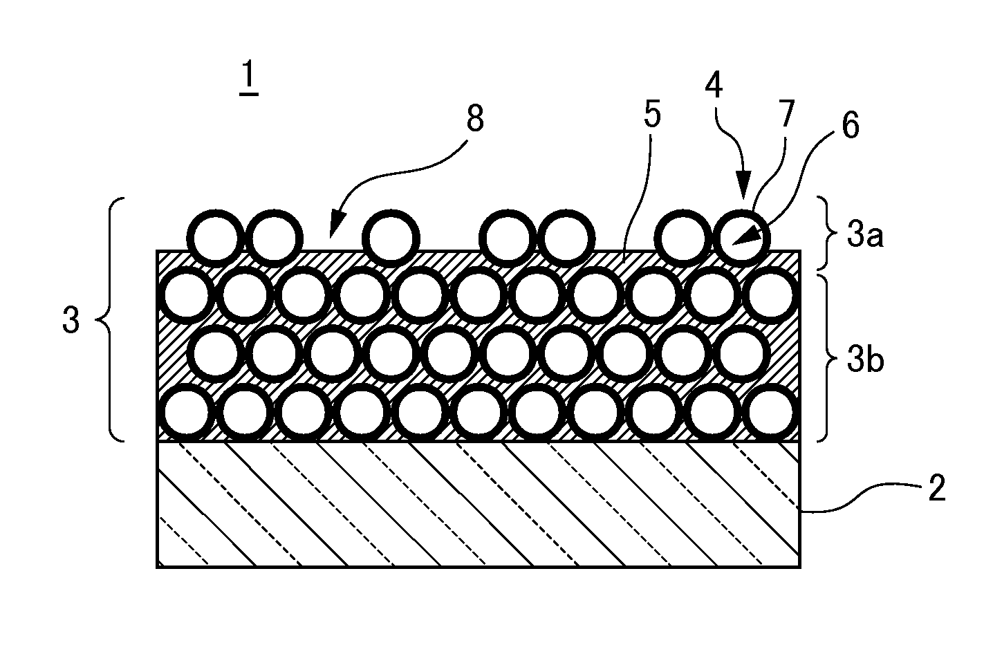
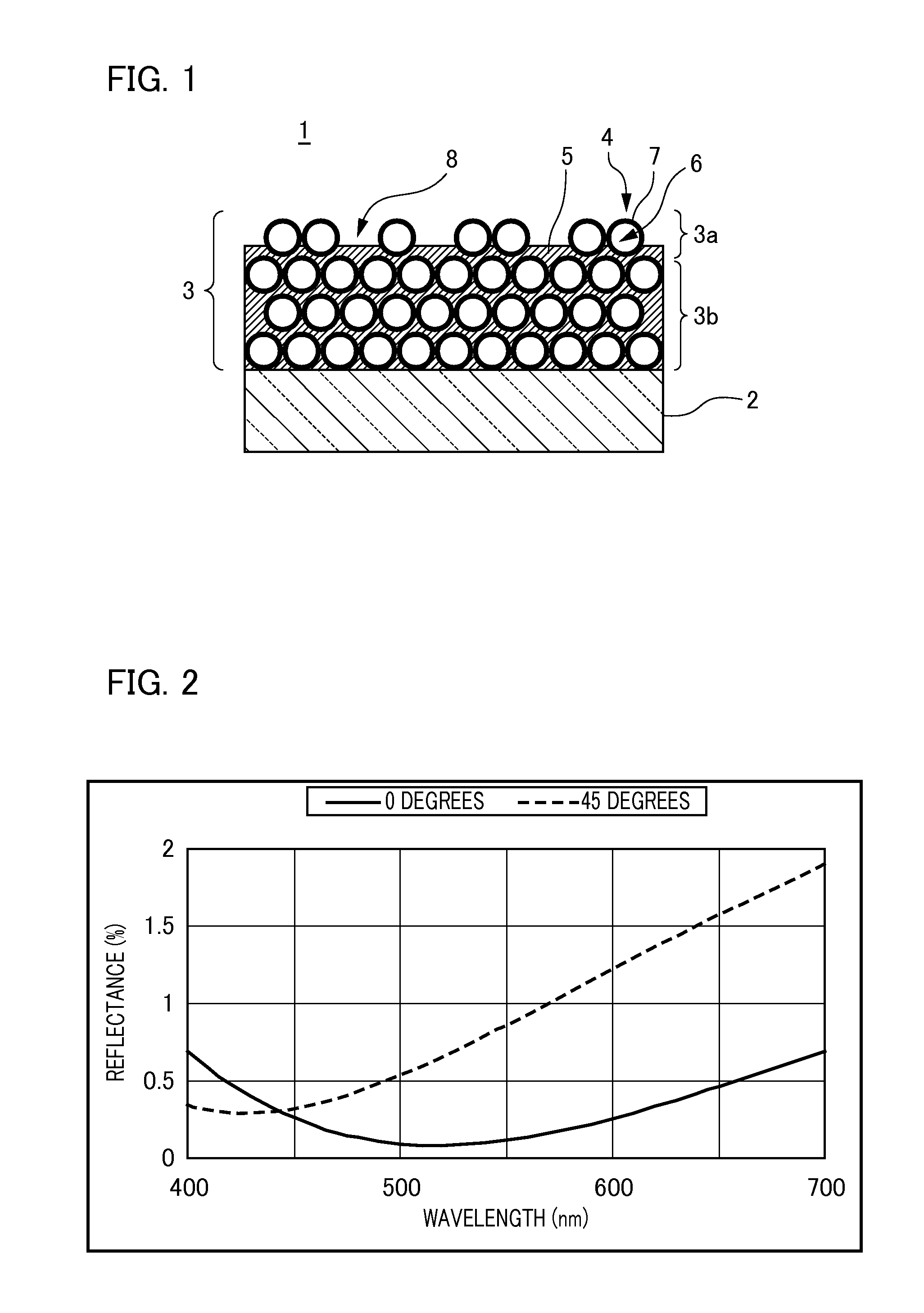
[0019]Firstly, a description will be given of an optical element according to a first embodiment of the present invention. FIG. 1 is a schematic cross sectional view illustrating the configuration of an optical element 1 according to the present embodiment. The optical element 1 includes a light-transmissive substrate (substrate) 2 and a low refractive index layer 3, i.e., an anti-reflection film, formed on the surface of the substrate 2 (on the substrate). Here, the term “anti-reflection film” refers to a film for increasing the amount of transmitted light and avoiding the occurrence of ghost and flare caused by unwanted light, which is formed on one side or both sides of the optical element employed in the imaging optical system of a photographing lens for use in an optical apparatus such as a video camera or the like. Firstly, the substrate 2 is a transparent member that consists of a glass such as quartz and a resin. For ease of explanation, the shape of the substrate 2 is a fla...

second embodiment

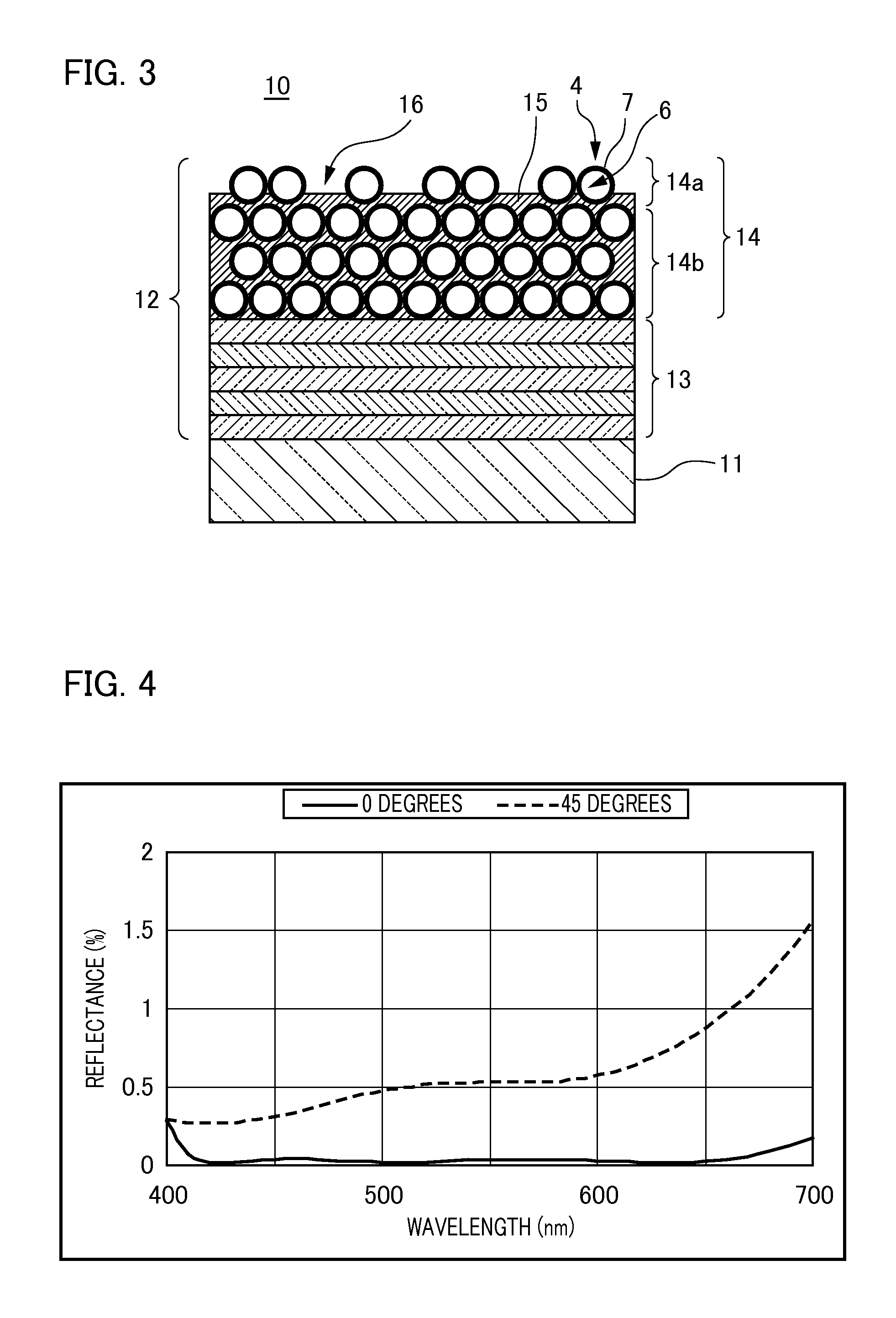
[0026]Next, a description will be given of an optical element according to a second embodiment of the present invention. Although the optical element 1 of the first embodiment only has the low refractive index layer 3 on the substrate 2, the optical element may also be configured such that a single layer or a plurality of layers such as a high refractive index layer, a middle refractive index layer, or the like is provided between the substrate 2 and the low refractive index layer 3. As the high refractive index layer or the middle refractive index layer, for example, a layer containing at least any one of materials selected from the group consisting of zirconium oxide, titanium oxide, tantalum oxide, niobium oxide, hafnium oxide, aluminum, silica, and magnesium fluoride is employed. Furthermore, a layer having functionality such as water repellency or oil repellency may be formed on the surface of the low refractive index layer 3, which is in contact with the external environment. ...


PUM

PropertyMeasurementUnit
refractive indexaaaaaaaaaa

Abstract

The optical element of the present invention has an anti-reflection film formed on a substrate. The anti-reflection film comprises a low refractive index layer that is formed by mutually binding hollow fine particles, each of which has a vacancy therein, using a binder, and the low refractive index layer consists of a first layer serving as an outermost layer and a second layer which is adjacent to the first layer and is located on the substrate side. Here, the filling ratio of the binder to the first layer is lower than the filling ratio of the binder to the second layer, the refractive index of the first layer is 1.1 or more but not more than 1.25 and the refractive index of the second layer is 1.26 or more but not more than 1.35

Description

BACKGROUND OF THE INVENTION[0001]1. Field of the Invention[0002]The present invention relates to an optical element, and an optical system and an optical apparatus using the same.[0003]2. Description of the Related Art[0004]Conventionally, an anti-reflection film for increasing the amount of transmitted light and avoiding the occurrence of ghost and flare caused by unwanted light has been coated on one side or both sides of the optical element employed in the imaging optical system provided in a photographing lens for use in an optical apparatus such as a video camera, a photographic camera, a television camera, or the like. In particular, for adaptation to high resolution such as high-definition (HD) of recent video cameras and television cameras and high image quality of recent photographic cameras, there is also a growing need for higher anti-reflection performance. Here, in order to obtain high anti-reflection performance, a material which is used for the outermost layer of an a...

Claims


Application Information

Patent Timeline
Patent Type & Authority Applications(United States)
IPC IPC(8): B32B7/02G02B1/02G02B1/11G02B1/111G02B1/118
CPCB32B7/02Y10T428/24942Y10T428/24975G02B1/118G02B1/14
Inventor AMANO, SAYOKOMOMOKI, KAZUHIKO
Owner CANON KK
Why Eureka
Try Eureka