Reagent refrigerator

a technology of reagent refrigerator and reagent, which is applied in the field of reagent refrigerator, can solve the problems of reducing the cooling and heating efficiency of the indoor space, the difficulty of moving the refrigerator, and the contaminated air of the indoor space where lots of experiment workers and researchers reside, so as to improve the flow of the inner circulation stream, reduce the quality and titer of the storage reagent, and improve the effect of air purification

Active Publication Date: 2013-02-14
GT SCIEN CO LTD
View PDF27 Cites 33 Cited by
  • Summary
  • Abstract
  • Description
  • Claims
  • Application Information

AI Technical Summary

Benefits of technology

[0029]The improved reagent refrigerator according to the present invention is capable of controlling the cooling temperature so as to minimize the decreases of quality and titer of storage reagents and is capable of smoothly and effectively purifying the air of the interior of the reagent storage compartment by improving the flow of the inner circulation stream while minimizing the differences of cooling temperatures. The present invention adapts a sealed circulation type structure, thus cutting off the inputs of the dusts from the outside, and the service live can be prolonged. It features in effective energy savings as compared to the open type structure. A uniform negative pressure is formed in the interior of the reagent storage cooling compartment when a user or a handler opens the door, so harmful gas or bad smell does not input from the reagent storage cooling compartment, and an open circulation structure can be partially adapted if needed, so an anti-explosion function can be provided. The defrosting and dehumidifying ope...

Problems solved by technology

In the above explained conventional reagent refrigerator, what the filter purification efficiency is lowered results in that the air of the indoor space where lots of experiment workers and researchers reside and work might be severely contaminated.
In addition, in case of the filter purification discharge type and the simple ventilation type reagent refrigerator, a duct is connected to the reagent refrigerator so as to avoid the indoor air contamination for thereby discharging the contaminated air to the outdoor space; however in this case the reagent refrigerator is hard to be moved, and since the indoor air is forcibly discharged to the outdoor space, the cooling and heating efficiency of the indoor space is lowered, and the outdoor space might be contaminated by the discharged harmful g...

Method used


Image

  • Reagent refrigerator
  • Reagent refrigerator
  • Reagent refrigerator

Examples


first embodiment

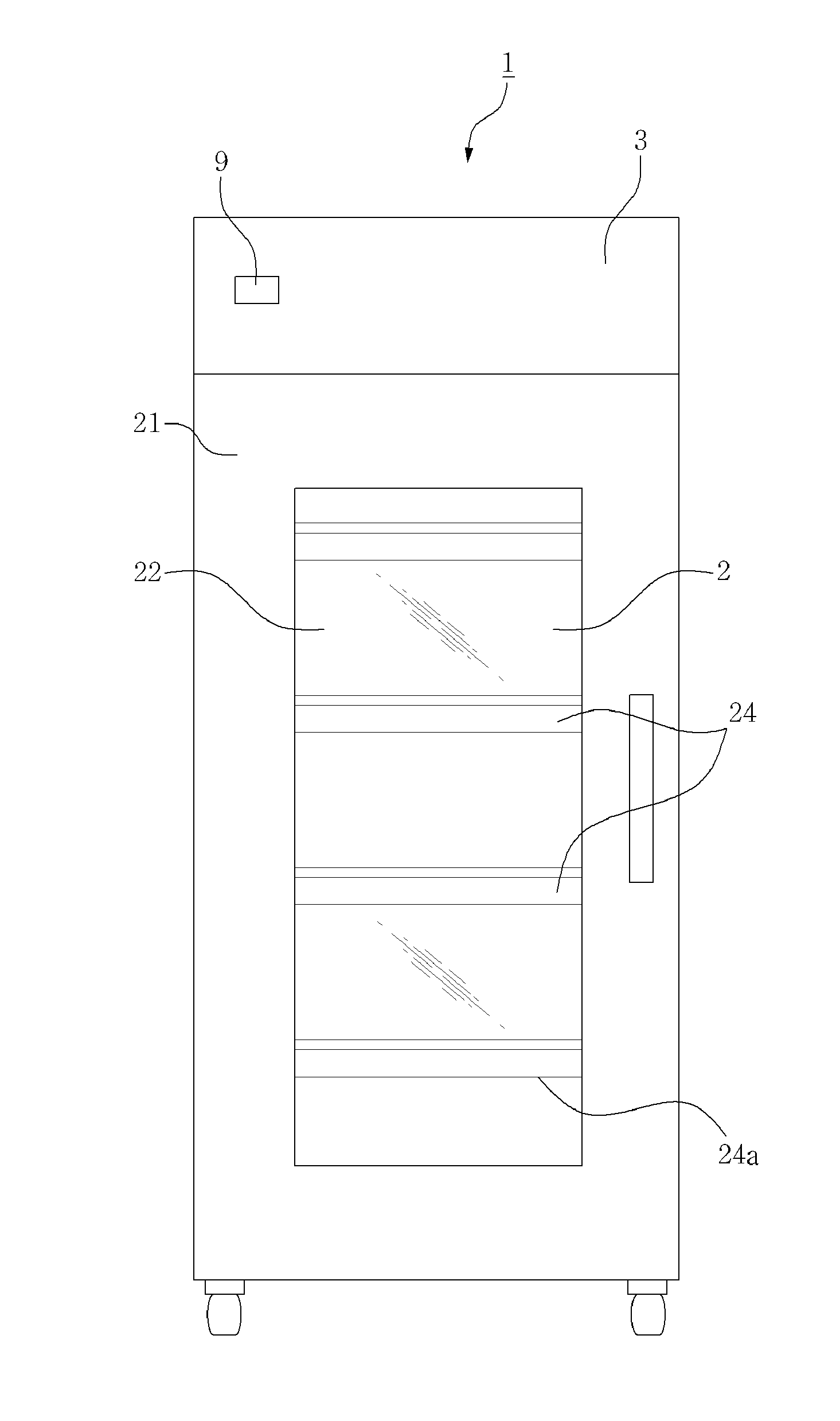
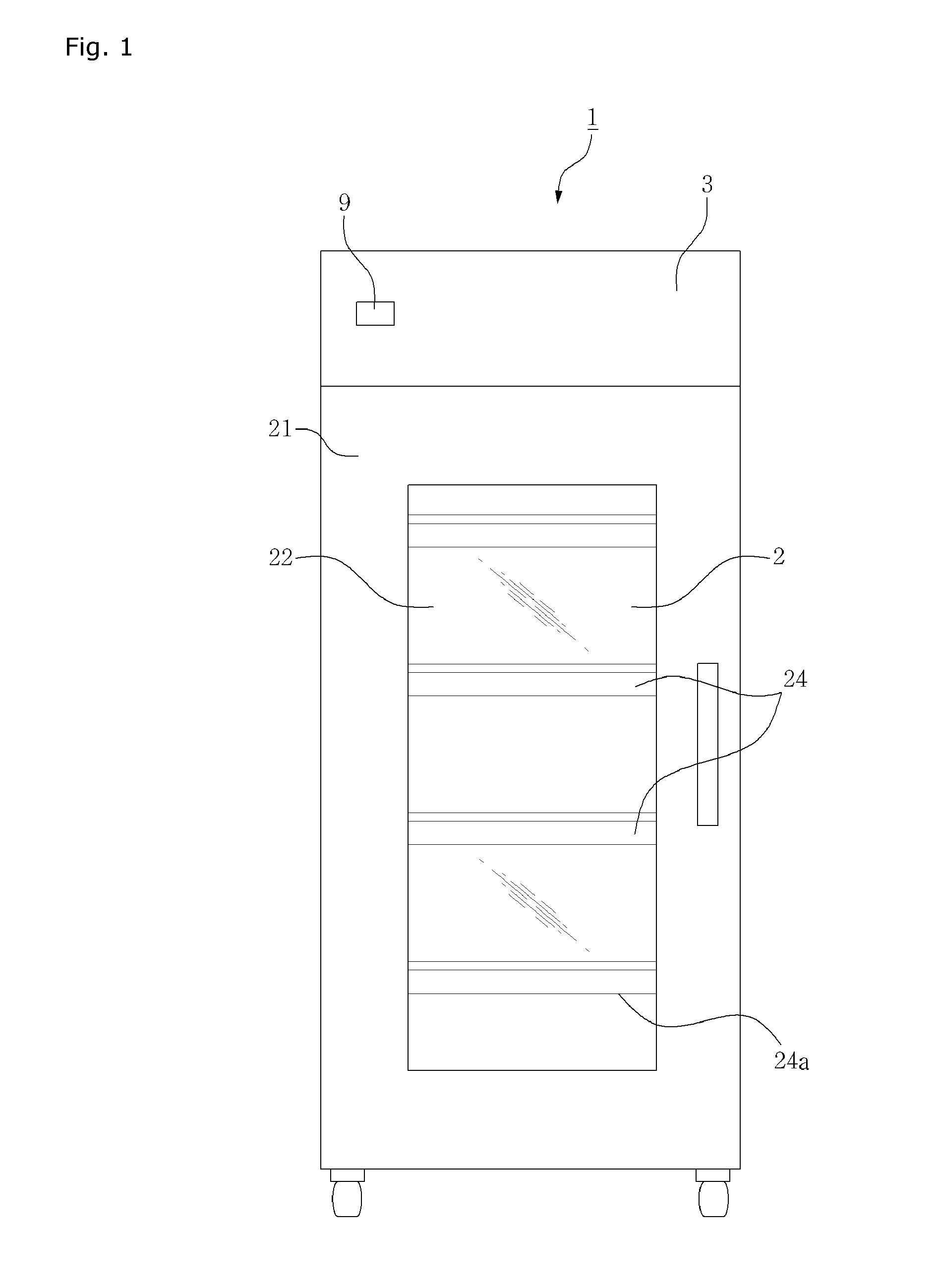
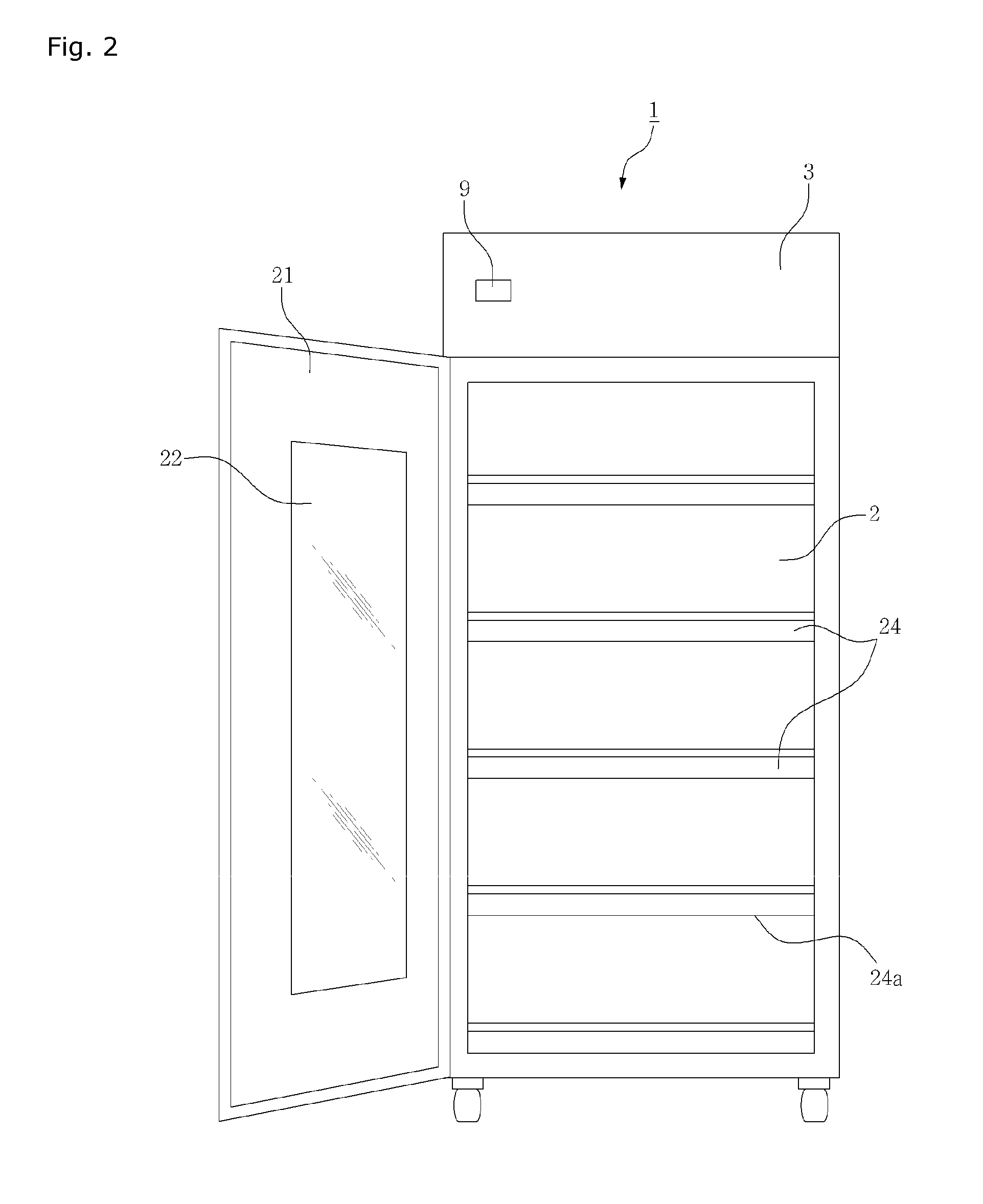
[0041]FIG. 3 is a front cross sectional view of a reagent refrigerator 1 according to the present invention. The reagent refrigerator 1 comprises a reagent storage cooling compartment 2 equipped with a plurality of reagent storage trays 24 which are installed in parallel, a cooling purification compartment 4 and a cooling device compartment 5. A housing 3 is provided above the reagent storage cooling compartment 2. First and second lateral ducts 6 and 6a and an upper duct 8 are provided at the left and right sides and upper side of the reagent storage cooling compartment 2, respectively.

[0042]A blower 41, filters 42a, 42b and 42c and an evaporator (heat exchanger) 44 are installed in the interior of the purification compartment 4 disposed at one side of the housing 3. The first to third filters 42a, 42b and 42c are installed in the interior of the filter housing 42 communicating with the upper duct 8 in a cartridge shape as they are sequentially stacked while forming upper and lower...

second embodiment

[0081]In the reagent refrigerator 1a according to the present invention as shown in FIGS. 4A and 4B, the flows of the air circulation stream in the reagent storage cooling compartment 2 and the cooling purification compartment 4 will be described. In the contaminated and heated air stream introduced from the upper duct 8, the purification cooling air stream (flow A) formed by the filters 4a, 42b and 42c and the evaporator 44 forms a downward air stream (flow B) by way of the lateral duct 6 by the blower 41 and forms a horizontal air stream (flow C) toward the stage of each tray 24 by way of the plurality of the through holes 62 of the lateral partition wall 61 and forms a downward air stream (flow D) by way of the net-shaped floor 24a of each tray 24, and the contaminated and heated air stream in the reagent storage cooling compartment 2 forms an upward air stream (flow E) in the rear duct 7 by way of a plurality of through holes 72 of the rear partition wall 71 of the rear duct 7 a...


PUM


Abstract

The present invention relates to a reagent refrigerator which comprises a reagent refrigerator compartment including reagent storing trays; an upper housing a cooling equipment compartment and a cooling purification compartment; a side duct defined by a side partition having a through hole at the side of the reagent refrigerator; one each of a second side duct, separately defined by a side partition having a through hole at the other side thereof, and a rear duct, separately defined by a rear partition having a through hole at the rear side thereof; and an upper duct having one end communication with the upper portion of the second side or rear side, and the other end communicating with the cooling purification compartment. Accordingly, refrigeration temperature of the reagent refrigerator can be controlled, and circulation flow in the reagent refrigerator is improved, to thereby purify the air therein and minimize deviations from refrigerator temperature values. In addition, since the reagent refrigerator is based on a closed circulation type structure, impurities are prevented from being introduced to the reagent refrigerator to thereby increase the service life of the filter and reduce energy consumption. Moreover, even when the door of the reagent refrigerator is opened, negative pressure distribution in the reagent refrigerator is relatively even, thereby preventing the emission of noxious gas and an offensive smell from the reagent refrigerator compartment to the indoor space. More particularly, the reagent refrigerator may be modified to have a partial opening circulation structure without a heater to thereby prevent explosions and to perform a defrosting/dehumidifying operation so that safety and economic feasibility can be improved. In addition, the reagent refrigerator can be automatically controlled and the internal condition of the reagent refrigerator compartment can be monitored in real time. Furthermore, not only can on-site/real-time control be executed, but remote control as well.

Description

BACKGROUND OF THE INVENTION[0001]1. Field of the Invention[0002]The present invention relates to a reagent refrigerator which provides a low temperature cooling storage for the sake of various experimental reagents generally used in the experimental rooms or research rooms of an university and a company under a safe and environment-friendly condition without an air contamination while minimizing the qualities of reagents and the decrease of titers, and in particular to a reagent refrigerant featuring in that a sealed circulation construction is obtained as a cooler housing is fluid-dynamically separated into a reagent storage cooling compartment and a filter purification compartment in a common cooling mode. In the defrosting and dehumidifying modes, they are partially communicated in a fluid-dynamical way without using a heater, thus obtaining an open circulation structure. The contaminated air in the reagent storage cooling compartment is forced to flow upward and is sucked into a...

Claims


Application Information

Patent Timeline
IPC IPC(8): F25D17/06F25D29/00
CPCB01L1/50B01L3/52B01L2200/082B01L2200/16B01L2300/1894F25D17/042F25D2317/041B01L2200/141F25D2317/0654F25D2317/0664F25D11/00F25D25/02F25D29/005
Inventor KANG, YEON KYUN
Owner GT SCIEN CO LTD
Why Eureka
Try Eureka