
Motor

a motor and motor body technology, applied in the field of motors, can solve the problems of large motor size, power cannot meet high requirements, bad magnetic accumulation effect, etc., and achieve the effect of small size, potent magnetic accumulation effect, and simple structur

Inactive Publication Date: 2013-02-14
ZHONGSHAN BROAD OCEAN MOTOR MFG
View PDF24 Cites 24 Cited by
  • Summary
  • Abstract
  • Description
  • Claims
  • Application Information

AI Technical Summary

Benefits of technology

The invention aims to provide a motor with a simple structure, small size, potent magnetic accumulation effect, and low cost. The motor has a rotor core with a larger thickness than the stator core, which helps to reduce magnetic leakage and lower cogging torque. The motor also utilizes a point with a distance deviating from the center of the central axial bore as the center of circle for the outer side surface, which helps to achieve a big counter-electromotive force constant and smooth waveform of the counter-electromotive force. As a result, the motor's performance is improved and losses are reduced.

Problems solved by technology

Such a structure has the disadvantage of bad magnetic accumulation effect, and the power cannot meet high requirements.
Generally, in order to meet the requirements of high power, the thickness of the rotor core and the stator core is increased, or other strong magnetic materials are employed, however, such methods would result in a large size of the motor, high cost, and lower the competitiveness.

Method used


Image

  • Motor
  • Motor
  • Motor

Examples


Embodiment Construction

[0024]The invention is explained in further detail below with reference to the accompanying drawings and examples.

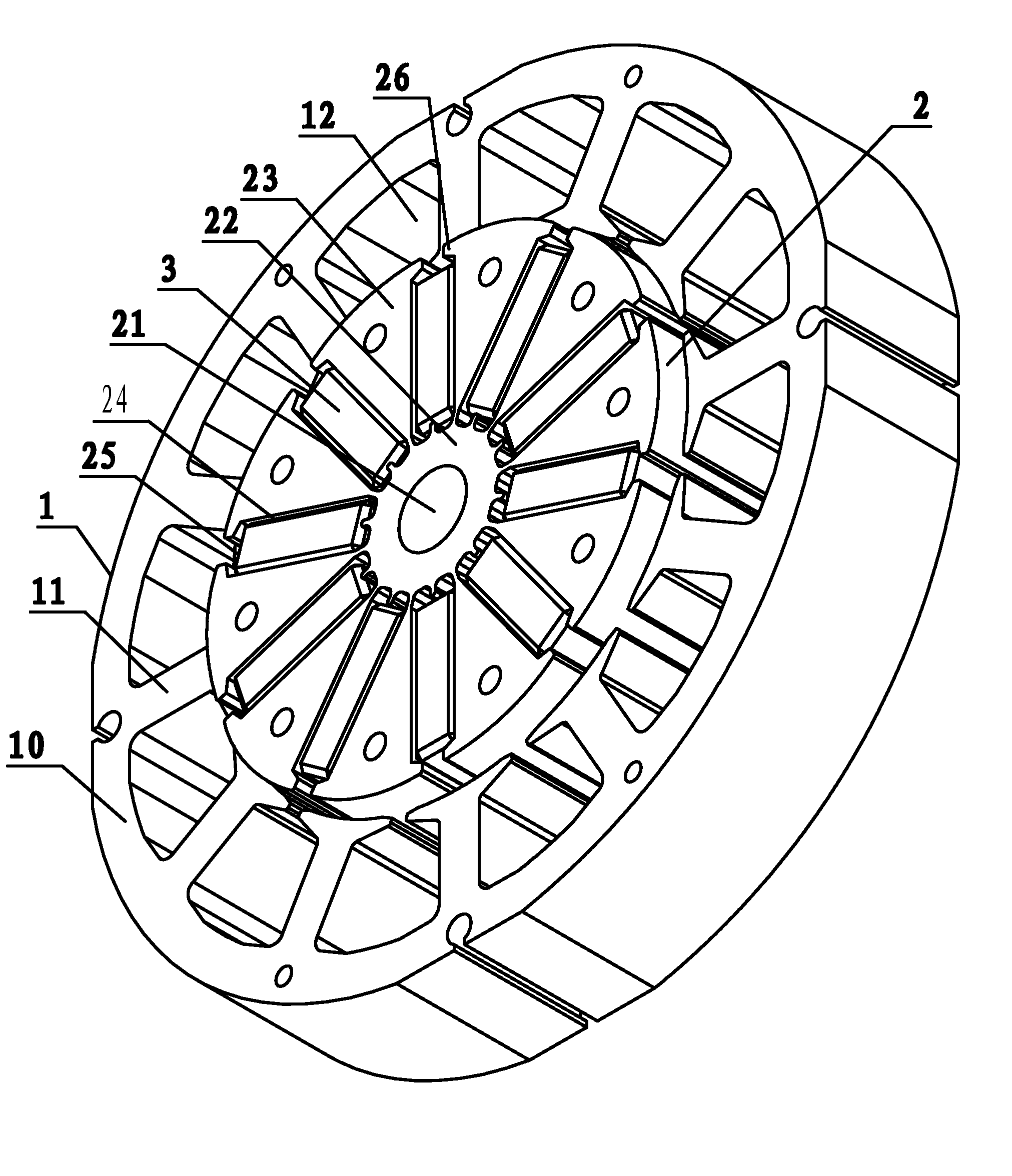
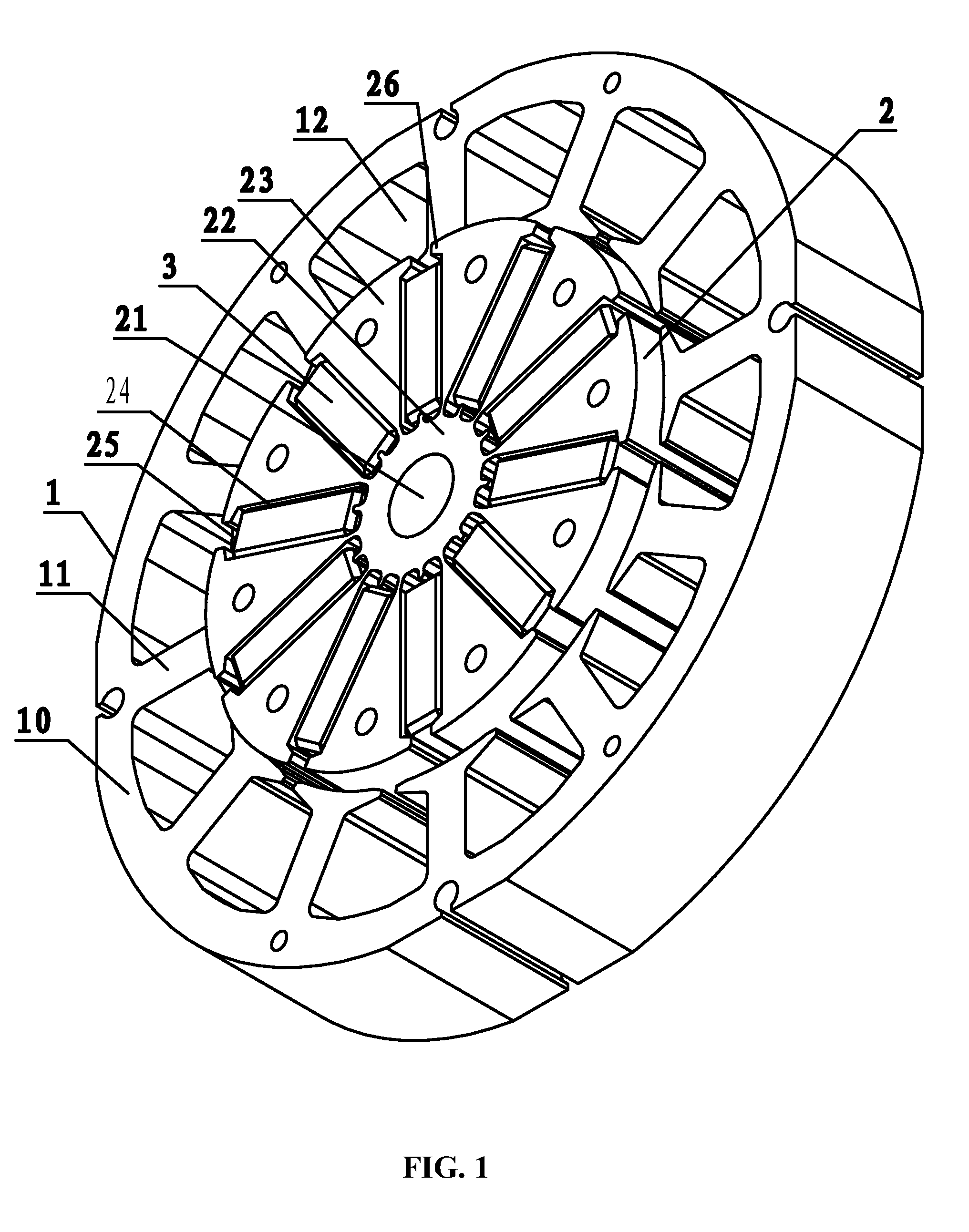
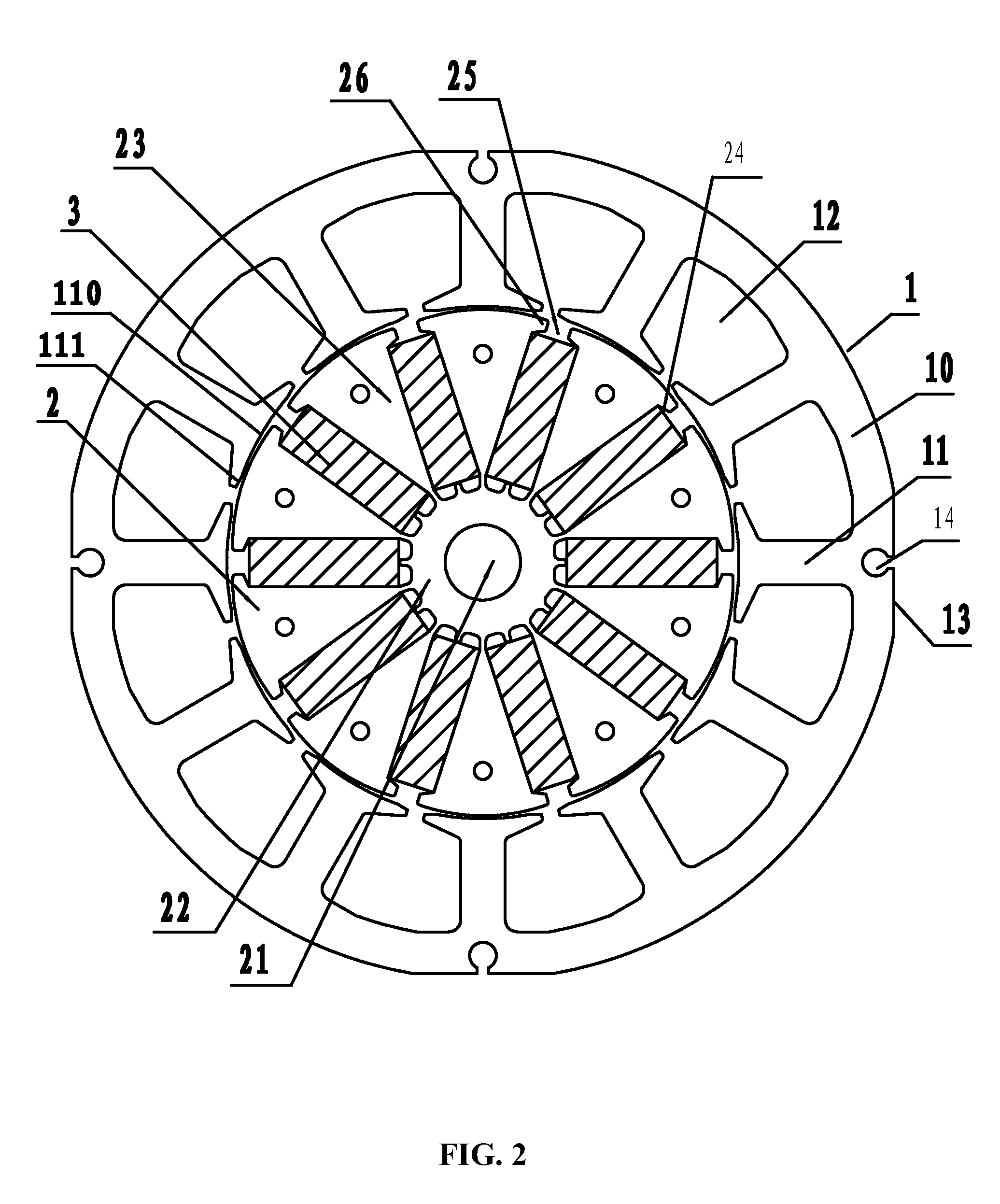
[0025]As shown in FIGS. 1-5, a motor comprises a stator assembly and a rotor assembly inserted into the stator assembly. The stator assembly comprises a stator core 1 and a winding; the stator core 1 comprises a yoke 10 and a plurality of teeth 11 protruding inwards from the yoke 10; between two adjacent teeth 11 formed is a winding slot 12; the winding is arranged in the winding slot 12, and winded on the teeth 11. The rotor assembly comprises a rotor core 2 and a permanent magnet 3; the rotor core 2 comprises an annular ring 22 having a central axial bore 21 and a plurality of magnetic induction blocks 23 protruding outwards from an outer side of the annular ring 22; between two adjacent magnetic induction blocks 23 formed is a radial recess 24 for mounting the permanent magnet 3; the magnetic induction blocks 23 at both sides of an opening 25 of the radial recess 24 p...


PUM


Abstract

A motor including a stator assembly and a rotor assembly. The stator assembly includes a stator core and a winding; the stator core includes a yoke and a plurality of teeth protruding inwards from the yoke; between two adjacent teeth formed is a winding slot; the winding is arranged in the winding slot, and winded on the teeth. The rotor assembly includes a rotor core and a permanent magnet. The rotor core includes an annular ring having a central axial bore and a plurality of magnetic induction blocks protruding outwards from an outer side of the annular ring. Between two adjacent magnetic induction blocks formed is a radial recess for mounting the permanent magnet. The magnetic induction blocks at both sides of an opening of the radial recess protrude with a hook block. The thickness of the rotor core is larger than that of the stator core.

Description

CROSS-REFERENCE TO RELATED APPLICATIONS[0001]This application is a continuation-in-part of U.S. application Ser. No. 13 / 292,054 filed Nov. 8, 2011, now pending, and claims the benefit of Chinese Patent Application No. 201120290991.3 filed Aug. 11, 2011 and Chinese Patent Application No. 201120398810.9 filed Oct. 19, 2011. The contents of all of the aforementioned applications, including any intervening amendments thereto, are incorporated herein by reference. Inquiries from the public to applicants or assignees concerning this document or the related applications should be directed to: Matthias Scholl P.C., Attn.: Dr. Matthias Scholl Esq., 14781 Memorial Drive, Suite 1319, Houston, Tex. 77079.BACKGROUND OF THE INVENTION[0002]1. Field of the Invention[0003]The invention relates to a motor.[0004]2. Description of the Related Art[0005]A conventional motor includes a stator assembly and a rotor assembly. The stator assembly includes a stator core and a winding, and the rotor assembly in...

Claims


Application Information

Patent Timeline
IPC IPC(8): H02K1/27
CPCH02K21/16H02K1/146H02K2201/03H02K1/06H02K2213/03
Inventor PAN, MINGPAN
Owner ZHONGSHAN BROAD OCEAN MOTOR MFG
Learn More