
Image-transmitting apparatus having a security function

a technology of security function and transmitting apparatus, which is applied in the direction of color television details, closed-circuit television systems, television systems, etc., can solve the problems of creating an economic burden on a customer, and the images captured by the camera are not clearly displayed on the screen

Inactive Publication Date: 2013-02-14
GUMMI ELECTRONICS
View PDF7 Cites 50 Cited by
  • Summary
  • Abstract
  • Description
  • Claims
  • Application Information

AI Technical Summary

Benefits of technology

The present invention solves problems in conventional image transmitting apparatus by providing a security function. The apparatus has a main body unit with an IP camera and a lamp module that is separate from the main body. The lamp module is inclined, allowing for maximum illumination. The lamp module can be easily separated and repaired in case of a fault. The camera captures clear images without being affected by the LED lamp. Additionally, the apparatus has a heat sink mounted at both the main body and the lamp module to release heat generated from the apparatus. This improves the lifespan of the main body and the lamp module. An emergency call device including a microphone and flashing light is also included for delivering emergency situations on the site.

Problems solved by technology

However, such a conventional security system has a limitation in that it should include a separate additional device, and creates an economic burden on a customer because a cost should be paid continuously if the security system is operated on the security service company basis.
In addition, the conventional security system also has a limitation in that since it is forcibly connected to an existing telephone being used, if necessary, a problem is caused at the time of mutual matching and a security device should be separately mounted if the security system is operated based on the individual security device that performs a sensing function merely through one sensor.
In addition, the conventional security system causes an inconvenience in that the entire main body should be removed from a prop on which the image security device is mounted upon the occurrence of a fault in the lamp module so as to repair the faulty lamp module.
In addition, the conventional security system entails a problem in that since light emitted from the lamp module adversely affects the camera, the images captured by the camera are not displayed clearly on a screen.

Method used


Image

  • Image-transmitting apparatus having a security function
  • Image-transmitting apparatus having a security function
  • Image-transmitting apparatus having a security function

Examples


Embodiment Construction

[0021]Hereinafter, the configuration and operation of an image transmitting apparatus according to the present invention will be described in more detail with reference to the accompanying drawings.

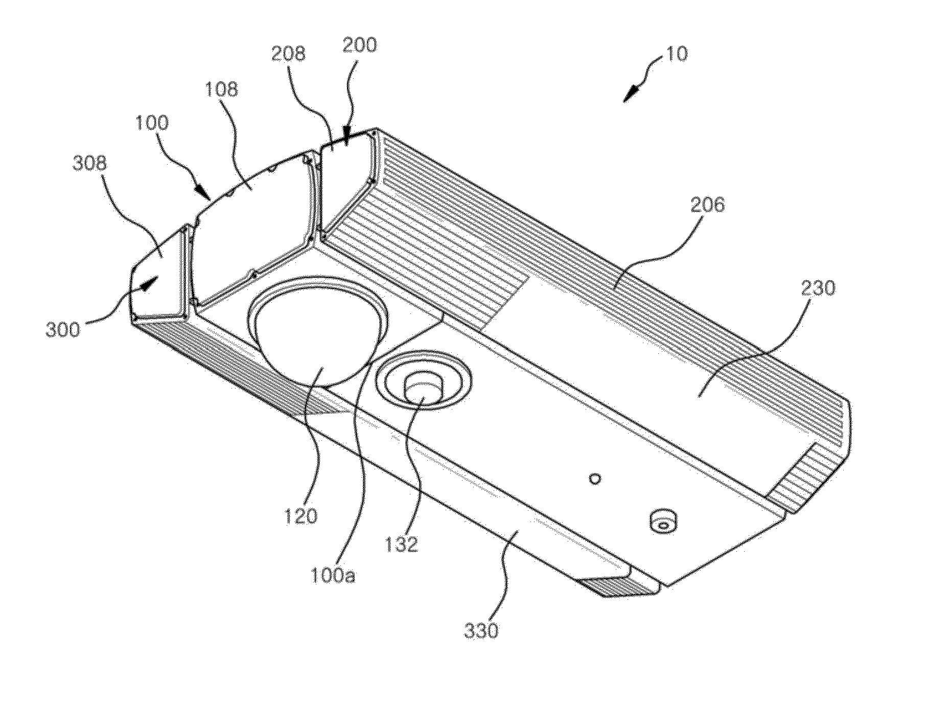
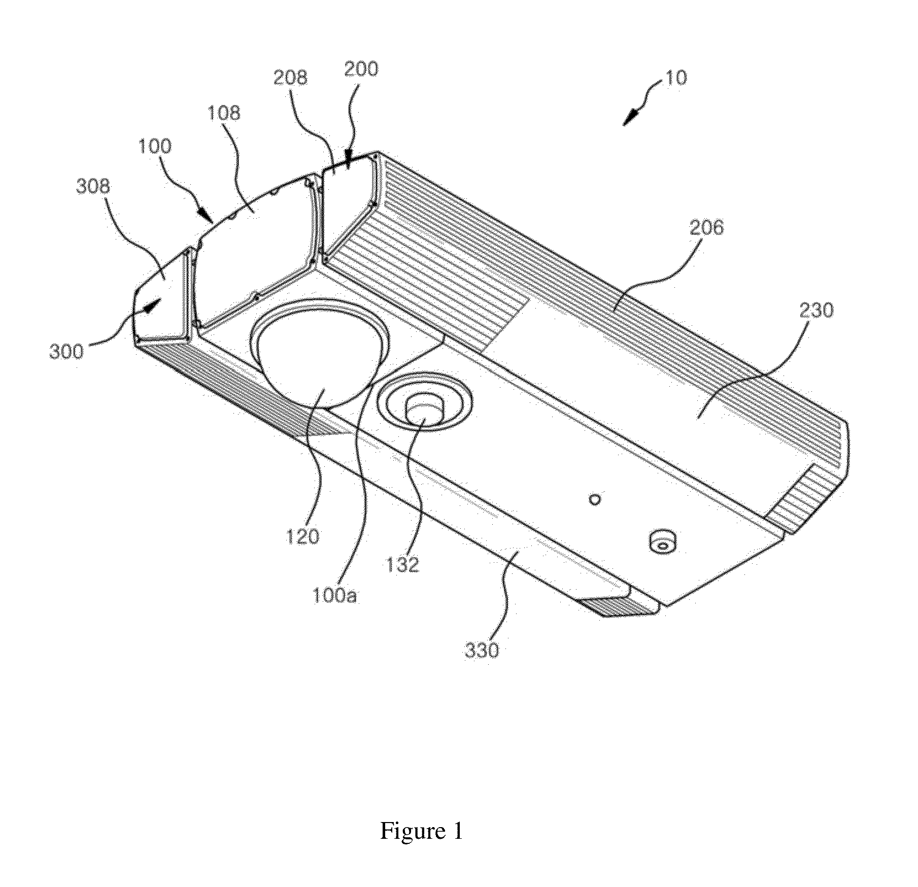
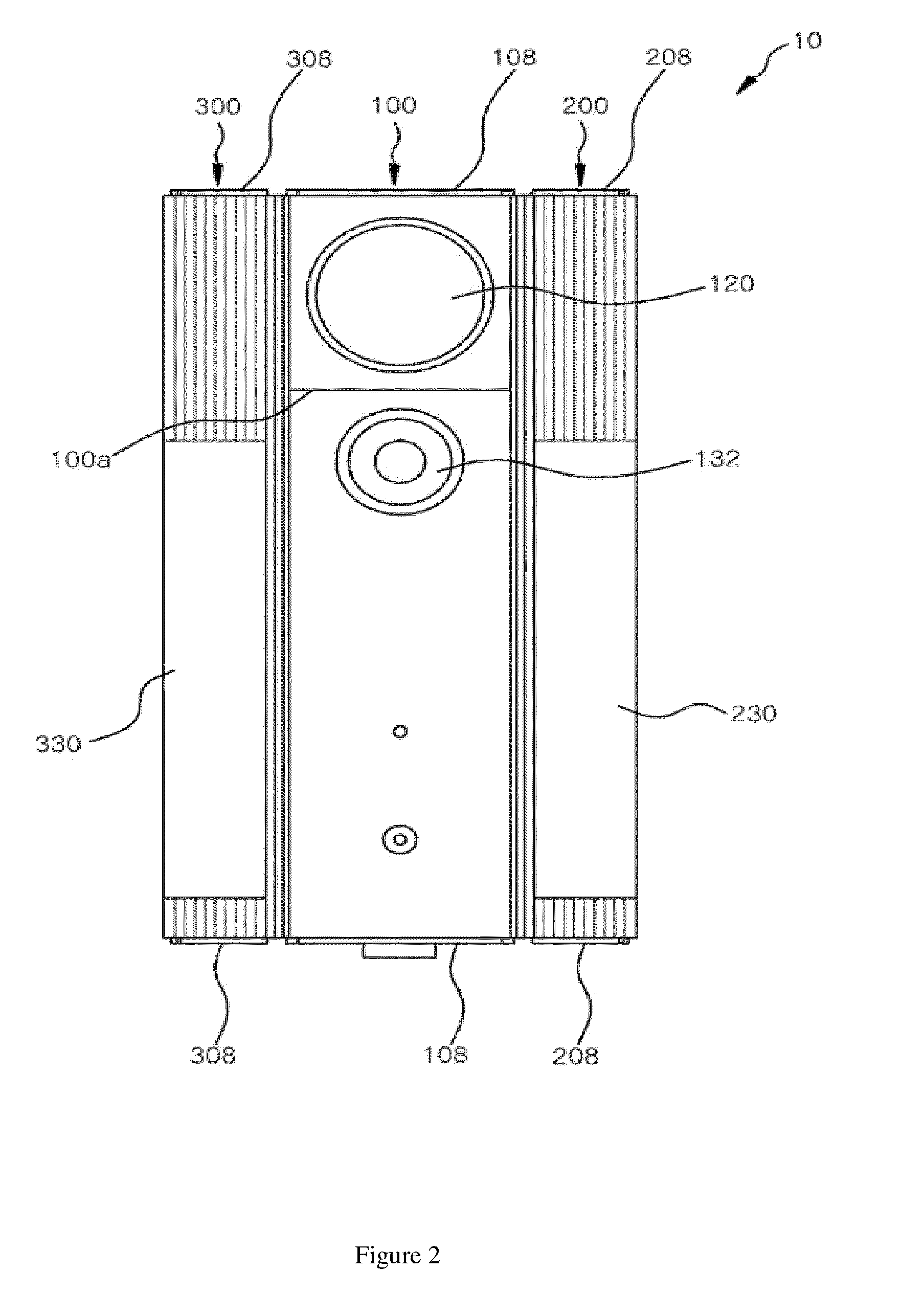
[0022]FIG. 1 is a bottom perspective view illustrating an image transmitting apparatus according to an embodiment of the present invention, FIG. 2 is a bottom view of FIG. 1, FIG. 3 is a front view of FIG. 1, and FIG. 4 is an exploded perspective view of FIG. 1.

[0023]Referring to FIGS. 1 to 4, an image transmitting apparatus 10 according to an embodiment of the present invention includes a main body unit 100 and a pair of lamp modules 200 and 300.

[0024]At an intermediate portion of each of both sides of the main body unit 100 is mounted a heat sink 102 that releases the heat generated from parts built in the main body unit 100 to the outside. A slide groove 104 is formed longitudinally in a horizontal direction at the upper and lower portions of both sides of the main body unit.

[0025]A re...


PUM


Abstract

An image-transmitting apparatus having a security function is provided. The image-transmitting apparatus having the security function includes a main body which is provided with a wireless or wired interface, a speaker, and an IP camera, either side of which having slide grooves formed in a horizontal direction in the upper and lower portions thereof; and lamp modules having LED lamps and sliders protruding so as to correspond to the respective slide grooves, such that the sliders are inserted into the respective slide grooves in order to couple the lamp modules to either side of the main body, respectively.

Description

CROSS-REFERENCE TO RELATED APPLICATIONS[0001]This application claims the benefit of Korean Patent Application No. 10-2010-0037090, filed on Apr. 21, 2010 in the Korean Intellectual Property Office, which is incorporated herein by reference in its entirety.BACKGROUND OF THE INVENTION[0002]1. Field of the Invention[0003]Exemplary embodiments of the present invention relate to a image transmitting apparatus having a security function, and more particularly, to such a image transmitting apparatus in which lamp modules including LED lamps are slidingly coupled to both sides of a main body including an IP camera.[0004]2. Description of Related Art[0005]Conventionally, a general security system adopts a method operated by a security service company employing a professional security system, i.e., a method in which a central sensing and receiving unit receives signals detected by various sensors, and transmits the received signals to a transmitting unit which in turn informs it to a control ...

Claims


Application Information

Patent Timeline
IPC IPC(8): H04N7/18
CPCH04N5/2256H04N5/2252H04N23/56H04N23/51
Inventor KIM, MYUNG-HWAN
Owner GUMMI ELECTRONICS
Learn More