
Eureka
For R&D, Eureka makes reading and utilizing patents & technical documents easy.
Eureka AIR
Designed for self-driven R&D workflows. Generate viable solutions, solve complex R&D challenges, empower your innovation with AI.

Eureka Materials
Designed for material experts only. Revolutionize your material R&D, from search, analyze, to developing new materials.

TechResearch
Generate reliable direction feasibility study reports for your R&D in just a few steps.

TechSeek
Discover and master advanced knowledge NOW. Basics, ideas, possibilities, all at once.

TechMind
As an expert in R&D Theories, TechMind can generates customized viable solutions instantly.

TechRisk
Analyze your overall solution with one click, know your potential R&D risks in advance.

TechMonitor
Get weekly tech updates, stay abreast of the latest tech innovations and key insights.
Variable wavelength interference filter, optical module, optical analysis device, and method for manufacturing variable wavelength interference filter
- Summary
- Abstract
- Description
- Claims
- Application Information
AI Technical Summary
Benefits of technology
Problems solved by technology
Method used
Image

Examples
first embodiment
[0037]Hereinafter, a colorimeter device as an optical analysis device of a first embodiment of the invention will be described with reference to the drawings.
1. Overall Configuration of Colorimeter Device
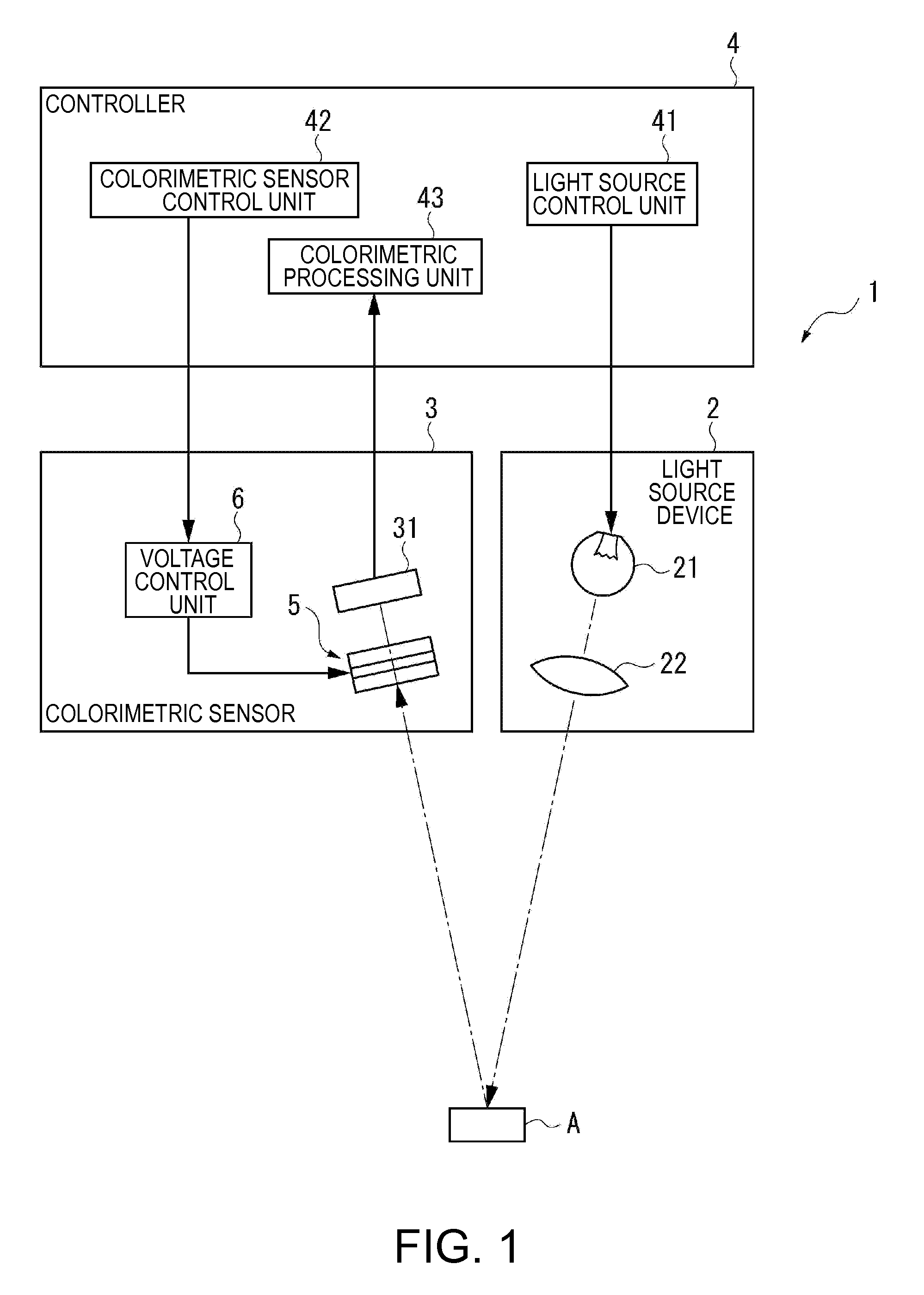
[0038]FIG. 1 shows a schematic configuration of the colorimeter device according to the first embodiment of the invention.
[0039]This colorimeter device 1 includes a light source device 2 which emits light to an inspection target A, a colorimetric sensor 3 as an optical module, and a controller 4 which controls overall operation of the colorimeter device 1, as shown in FIG. 1. In this colorimeter device 1, light emitted from the light source device 2 is reflected on the inspection target A and the reflected inspection target light is received by the colorimetric sensor. Based on a detection signal outputted from the colorimetric sensor 3, chromaticity of the inspection target light, that is, the color of the inspection target A, is analyzed and measured.
2. Configuration of Light Sour...
second embodiment
[0089]Next, a variable wavelength interference filter according to a second embodiment of the invention will be described.
[0090]FIG. 5 is a sectional view showing a schematic configuration of an etalon according to the second embodiment. In the following description of the second embodiment, the same components of the configuration in the first embodiment are denoted by the same reference numerals and the description thereof will be omitted or simplified.
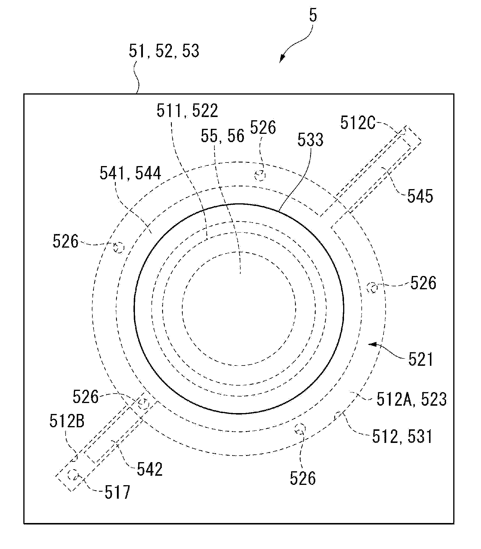
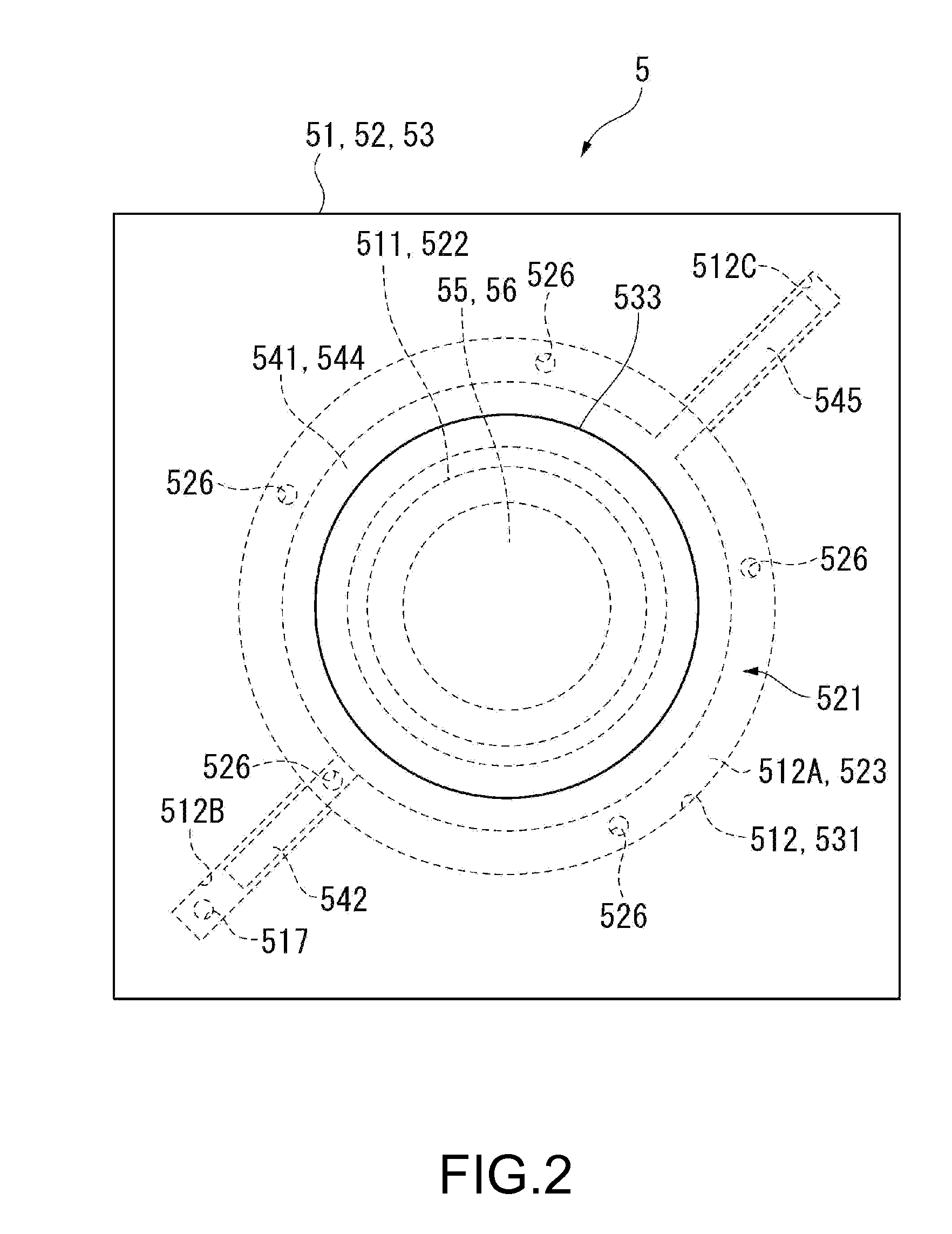
[0091]The colorimeter device of the second embodiment has substantially the same configuration as in the first embodiment and includes the light source device 2, the colorimetric sensor 3, and the controller 4. The second embodiment is different from the first embodiment in the configuration of an etalon 5A provided in the colorimetric sensor 3.
[0092]That is, in the etalon 5 of the first embodiment, the second penetration hole 526 is provided in the second substrate 52, whereas in the etalon 5A of the second embodiment, the second p...
third embodiment
[0098]Next, a variable wavelength interference filter according to a third embodiment of the invention will be described.
[0099]FIG. 6 is a sectional view showing a schematic configuration of an etalon according to the third embodiment.
[0100]FIG. 7 is a schematic view for explaining a process of sealing an internal space of the etalon of the third embodiment.
[0101]In the first embodiment, the penetration holes 517, 526 connecting the light exiting-side space 581 to an outside space are provided separately from the holes for forming the penetration electrodes 514A, 514B, and the first penetration hole 517 is sealed where the light incident-side space 582 and the light exiting-side space 581 are in a reduced-pressure state. The bump electrode 516 is formed, and the displacement electrodes 541, 544 are connected to the external terminals 515A, 515B via the penetration electrodes 514A, 514B and the bump electrode 516.
[0102]Meanwhile, in the third embodiment, a first electrode forming hol...
PUM
| Property | Measurement | Unit |
|---|---|---|
| Pressure | aaaaa | aaaaa |
| Wavelength | aaaaa | aaaaa |
| Optical properties | aaaaa | aaaaa |
Abstract
Description
Claims
Application Information
 - R&D Engineer
- R&D Manager
- IP Professional
- Industry Leading Data Capabilities
- Powerful AI technology
- Patent DNA Extraction
Browse by: Latest US Patents, China's latest patents, Technical Efficacy Thesaurus, Application Domain, Technology Topic, Popular Technical Reports.
© 2024 PatSnap. All rights reserved.Legal|Privacy policy|Modern Slavery Act Transparency Statement|Sitemap|About US| Contact US: help@patsnap.com