Color filter array and manufacturing method thereof

a technology of color filter and color ink, which is applied in the field of color filter array, can solve the problems of high cost of photolithography process, inability to evenly or flatly fill unit regions with color ink, and waste of most color photo resist materials, so as to improve the color display performance of the display, the effect of lessening the difference in film thickness of color filter patterns

Active Publication Date: 2013-02-14
AU OPTRONICS CORP
View PDF1 Cites 11 Cited by
  • Summary
  • Abstract
  • Description
  • Claims
  • Application Information

AI Technical Summary

Benefits of technology

[0007]Accordingly, the invention is directed to a color filter array and a manufacturing method thereof capable of ...

Problems solved by technology

However, the spinning coating process is prone to waste most color photo resist material, and costs of performing the photolithography process are high.
However, when the color filter array is formed by performing the IJP process, the cohesion of the color ink itself is greater than the adhesion between t...

Method used


Image

  • Color filter array and manufacturing method thereof
  • Color filter array and manufacturing method thereof
  • Color filter array and manufacturing method thereof

Examples


Embodiment Construction

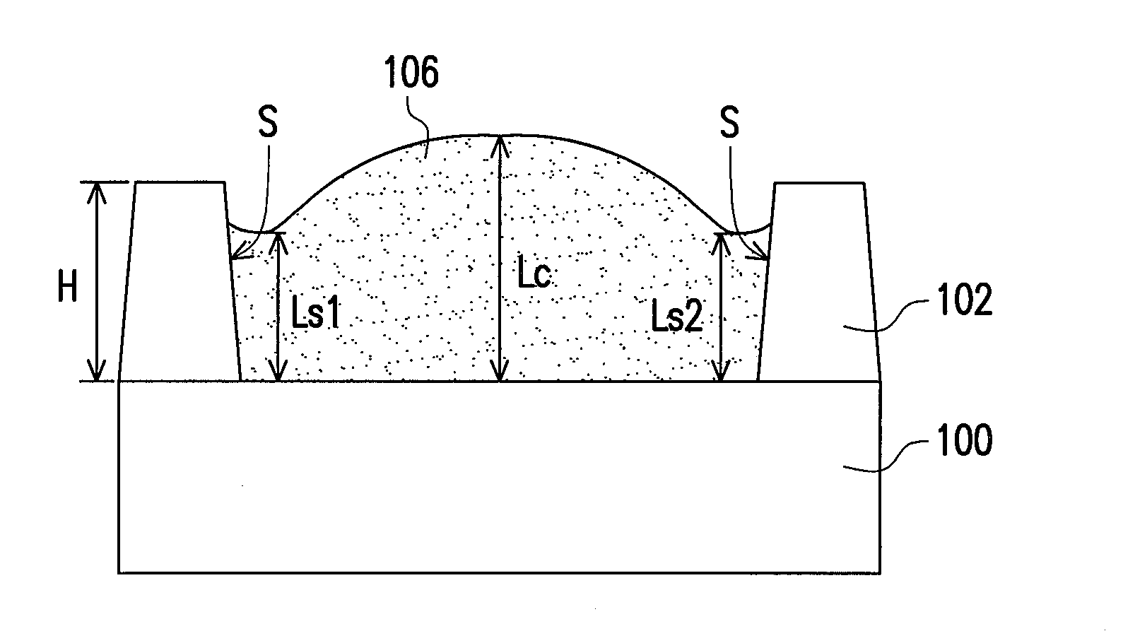
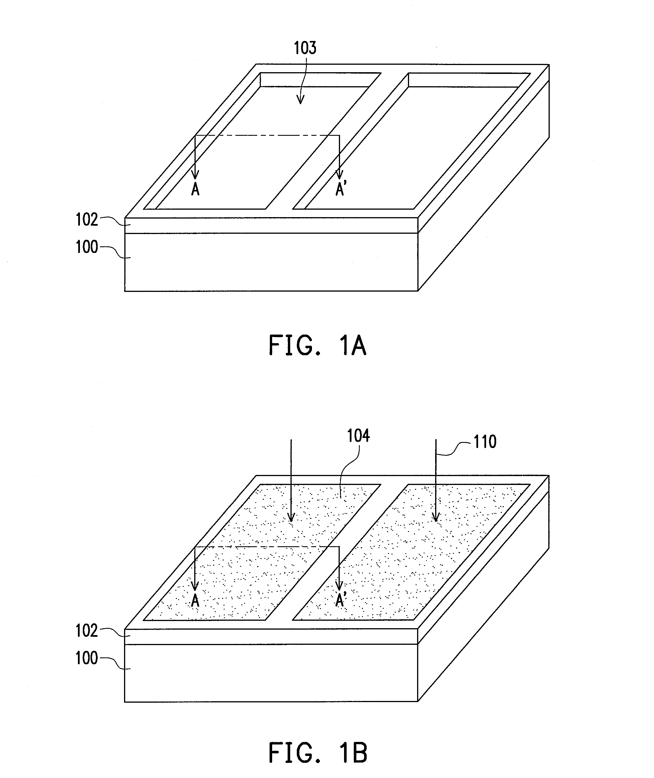
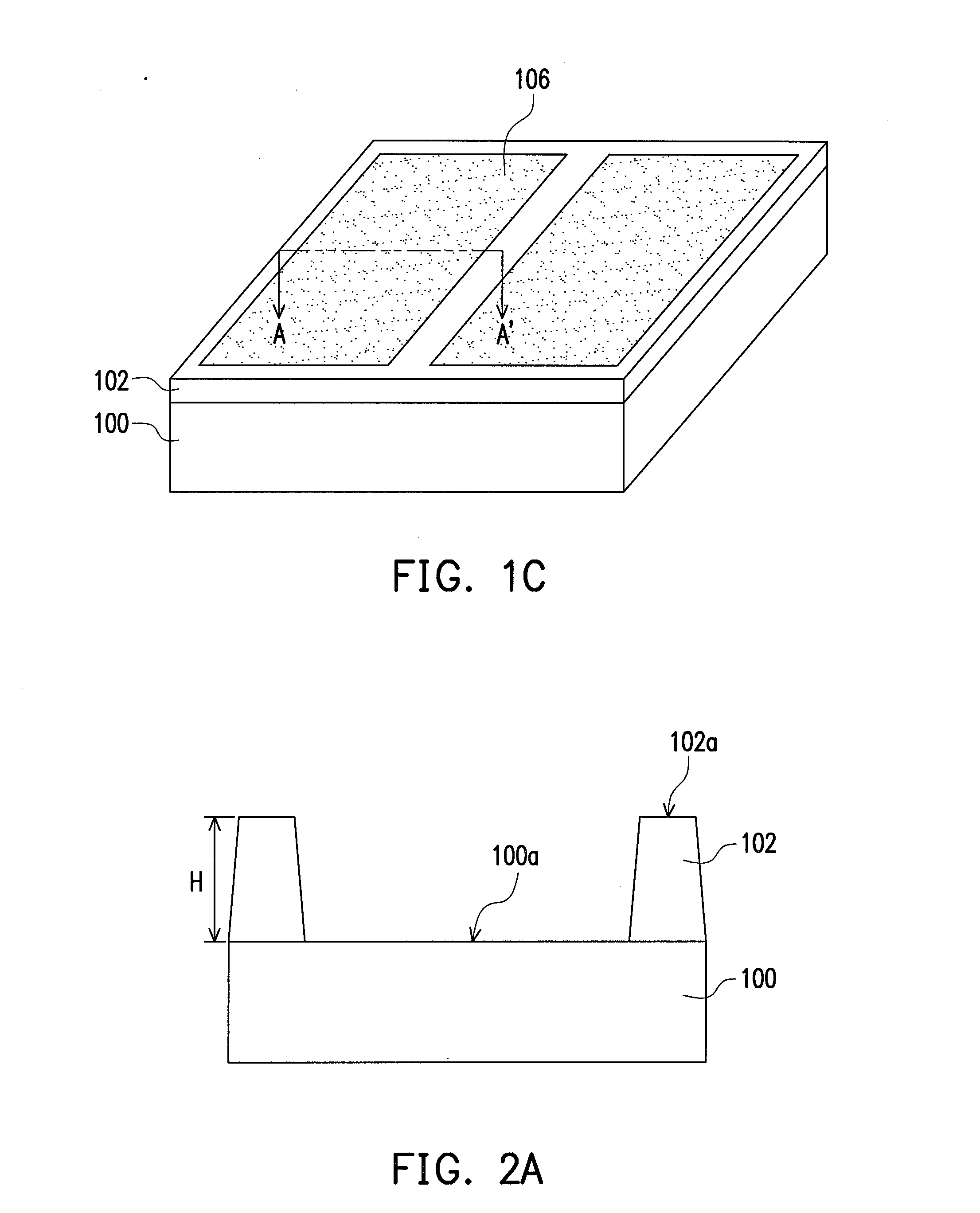
[0017]FIG. 1A to FIG. 1C are schematic views illustrating a manufacturing process of a color filter array according to an embodiment of the invention. FIG. 2A to FIG. 2C are schematic cross-sectional views taken along a cross-sectional line A-A′ depicted in FIG. 1A to FIG. 1C. With reference to FIG. 1A and FIG. 2A, in the manufacturing method of the color filter array described in this embodiment, a substrate 100 is provided. The substrate 100 can be made of glass, quartz, an organic polymer, a non-light-transmissive / reflective material (such as a conductive material, metal, wafer, ceramics, or the like), or other suitable materials. Besides, the substrate 100 can be a simple blank substrate or a substrate on which other film layers or devices are formed. If the substrate 100 is a simple blank substrate, a simple color filter array is formed at last. However, a substrate having other film layers or devices (e.g., a pixel array) thereon can be formed on the simple color filter array....


PUM


Abstract

A color filter array includes a substrate, a light shielding layer, and color filter patterns. The light shielding layer is on the substrate and has openings exposing a surface of the substrate. Besides, the light shielding layer has a height H. The color filter patterns are located in the openings of the light shielding layer. Each color filter pattern has the maximum film thickness Lc and the minimum film thickness Ls, and the difference between the maximum film thickness Lc and the minimum film thickness Ls is ΔL. The maximum film thickness Lc of each color filter pattern satisfies (m×H)<Lc<(n×H), wherein m comprises about 0.83, n comprises about 0.91, the height H of the light shielding layer satisfies a<H<b, wherein a comprises about 1.6 um and b comprises 2.22 um, and the difference ΔL is less than about 0.39 um.

Description

CROSS-REFERENCE TO RELATED APPLICATION[0001]This application claims the priority benefit of Taiwan application serial no. 100128930, filed on Aug. 12, 2011. The entirety of the above-mentioned patent application is hereby incorporated by reference herein and made a part of this specification.BACKGROUND OF THE INVENTION[0002]1. Field of the Invention[0003]The invention relates to a color filter array and a manufacturing method thereof. More particularly, the invention relates to a color filter array formed by performing an inkjet printing (IJP) process and a manufacturing method of the color filter array.[0004]2. Description of Related Art[0005]A color filter array of a normal display device is manufactured by performing a spinning coating process and a photolithography process to form red, green, and blue photo resist patterns that are arranged in arrays. However, the spinning coating process is prone to waste most color photo resist material, and costs of performing the photolithog...

Claims


Application Information

Patent Timeline
IPC IPC(8): G02B5/22B05D3/10B05D5/06
CPCB41J2202/09G02F1/133512G02B2207/123G02B5/201G02F1/133516
Inventor LIN, SHIUAN-FULIN, CHENG-YUE
Owner AU OPTRONICS CORP
Why Eureka
Try Eureka