Congestion control in an optical line terminal

a technology of optical line terminals and control devices, applied in data switching networks, frequency-division multiplexes, instruments, etc., can solve problems such as congestion and congestion in the ol

a technology of optical line terminals and control devices, applied in data switching networks, frequency-division multiplexes, instruments, etc., can solve problems such as congestion and congestion in the ol

US20130039182A1Active Publication Date: 2013-02-14REALTEK SINGAPORE PTE LTD

Image

  • Congestion control in an optical line terminal
  • Congestion control in an optical line terminal
  • Congestion control in an optical line terminal

Examples


Embodiment Construction

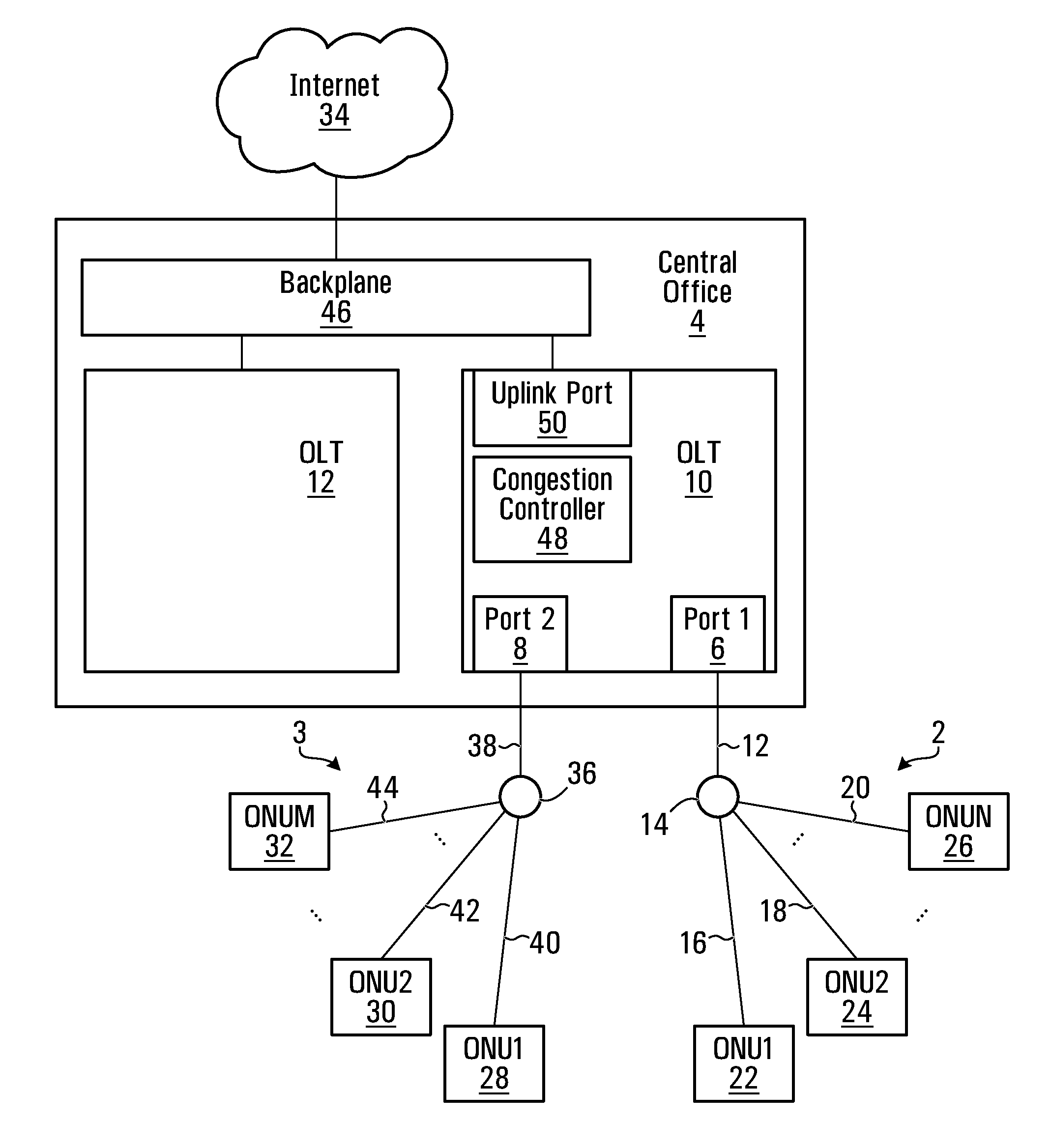
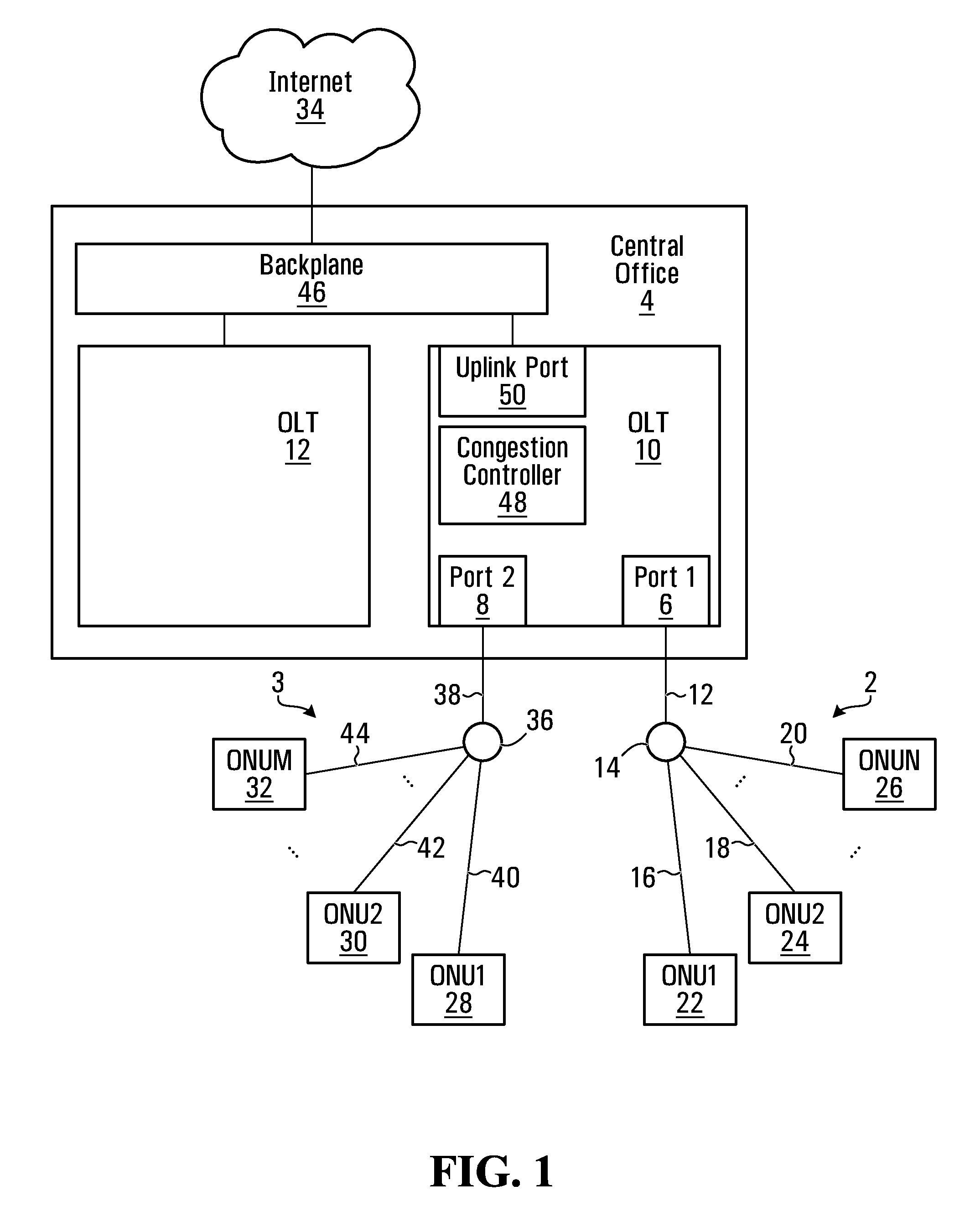
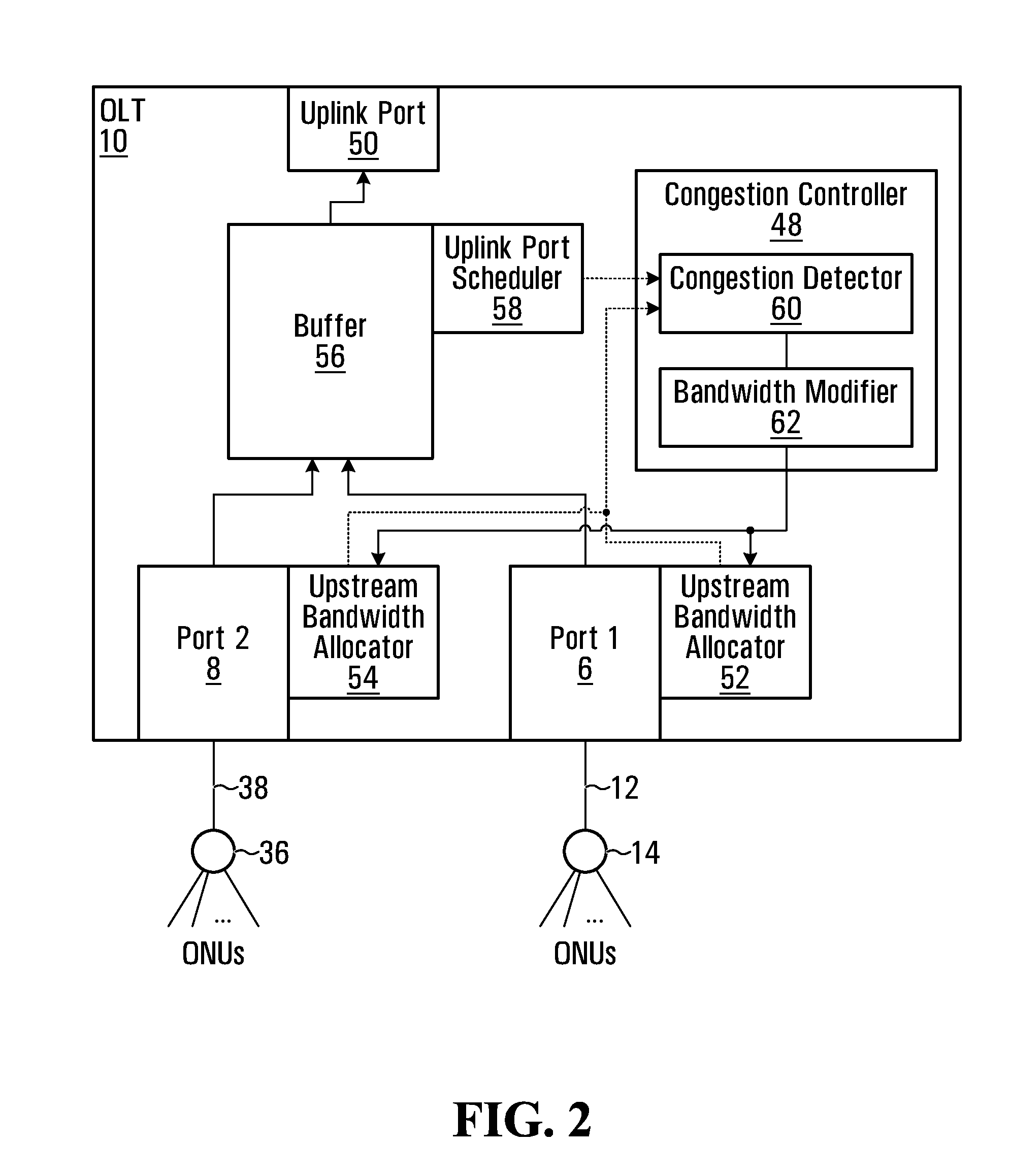
[0023]In general, there are disclosed methods and systems for managing congestion in an Optical Line Terminal (OLT). The OLT has a plurality of ports, each of which is used for communicating with at least one Optical Network Unit (ONU). Each of these ports has a respective enforced maximum upstream bandwidth. The OLT further includes an uplink port through which data received from each of the plurality of ports are transmitted. If it is determined that there is congestion of the data in the OLT queued for transmission through the uplink port, then the enforced maximum upstream bandwidth for at least one of the ports interfacing with the ONUs is modified. This can have the benefit of reducing congestion in the OLT, since the total amount of data received at the OLT from the ONUs can be reduced while the enforced maximum upstream bandwidth is modified. For example, in one example embodiment, a lower maximum upstream bandwidth may be enforced at each of the ports by reducing the number...


PUM


Abstract

There are disclosed systems and methods for detecting and controlling congestion in an Optical Line Terminal (OLT). The OLT has a plurality of ports. Each port of the plurality of ports communicates with at least one Optical Network Unit (ONU), and each port of the plurality of ports has a respective enforced maximum upstream bandwidth. For example, the maximum upstream bandwidth may be enforced by a Dynamic Bandwidth Allocation (DBA) algorithm. The OLT further includes an uplink port through which data received from each of the plurality of ports are transmitted. In one embodiment, if there is congestion of the data at the uplink port, then the enforced maximum upstream bandwidth for at least one port of the plurality of ports is modified.

Description

FIELD[0001]This application relates to passive optical networks.BACKGROUND[0002]Access networks connect business and residential subscribers to the central offices of service providers, which in turn are connected to metropolitan area networks (MANs) or wide area networks (WANs). Often, these access networks are hybrid fiber coax (HFC) systems with an optical fiber based feeder network between the central office and a remote node, and an electrical distribution network between the remote node and subscribers. In so-called “Fiber-to-the-x” (FTTx) access networks, the copper-based distribution part of the access network is replaced with optical fiber, e.g., fiber-to-the-curb (FTTC) or fiber-to-the-home (FTTH). In doing so, the capacity of the access network is increased.[0003]Passive optical networks (PONs) are optical networks that can be used in such applications. A PON is a point-to-multipoint, fiber to the premises network architecture in which unpowered optical splitters are used...

Claims


Application Information

Patent Timeline
14 Feb 2013
Publication
US20130039182A1
IPC
H04L12/24; H04J14/00; H04L12/26
CPC
H04L41/0816; H04L47/14; H04Q2011/0064; H04Q11/0067; H04W8/04
Inventors
DAS, ABHIMANYU; LEE, EUGENE