
Decomposing hyperspectral or multispectral image data

a multi-spectral image and data technology, applied in the field of electronic image processing, can solve the problems of difficult determination of the underlying endmember, inability to use methods, and difficulty in finding any underlying spectra in the radiance spectra, and achieve the effect of greater us

Active Publication Date: 2013-02-14
NAT ICT AUSTRALIA
View PDF2 Cites 24 Cited by
  • Summary
  • Abstract
  • Description
  • Claims
  • Application Information

AI Technical Summary

Benefits of technology

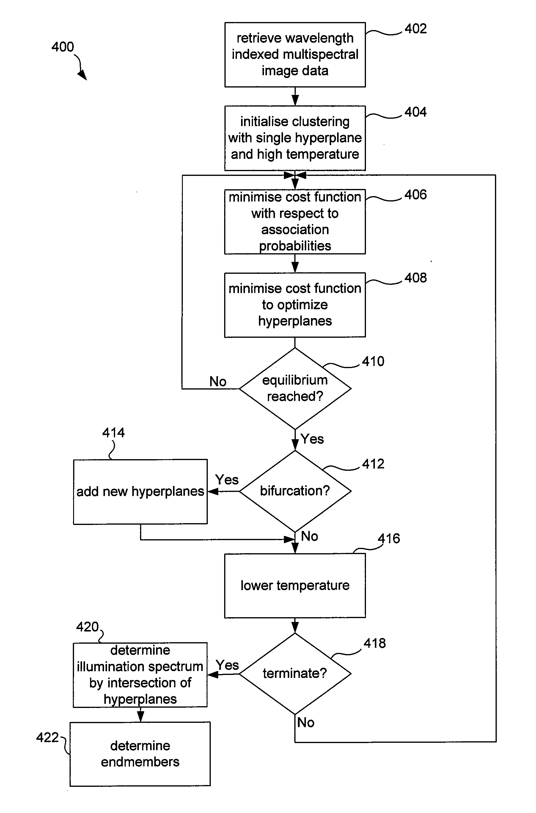
The patent text describes a method for decomposing images into multiple hyperplanes and contributions. These hyperplanes carry more information about the image, such as the illumination spectrum. The decomposition can be done without knowledge of the illumination spectrum and allows for new applications such as endmember extraction and compact representation. The method optimizes a cost function based on entropy to maximize the independence of the basis vectors of the hyperplanes and prevent the method from determining an association probability for only one hyperplane in cases where the image spectrum is a mixture of more than one independent hyperplanes. The method can also determine the reflectance spectrum of each hyperplane, enabling the identification of materials present at each pixel location. The compact representation of the decomposed image is stored on a computer-readable medium for easy access by processors or other computer systems.

Problems solved by technology

It is difficult to find any underlying spectra in the radiance spectra and these underlying spectra are not the material reflectance spectra unless the illumination spectrum is also considered.
In the resulting multi-dimensional sample space, the determination of the underlying endmembers is difficult.
One problem with existing approaches is that the underlying spectra, such as endmember spectra, need to be provided to the method as an input.
If the underlying spectra are not known, these methods cannot be used.

Method used


Image

  • Decomposing hyperspectral or multispectral image data
  • Decomposing hyperspectral or multispectral image data
  • Decomposing hyperspectral or multispectral image data

Examples


Embodiment Construction

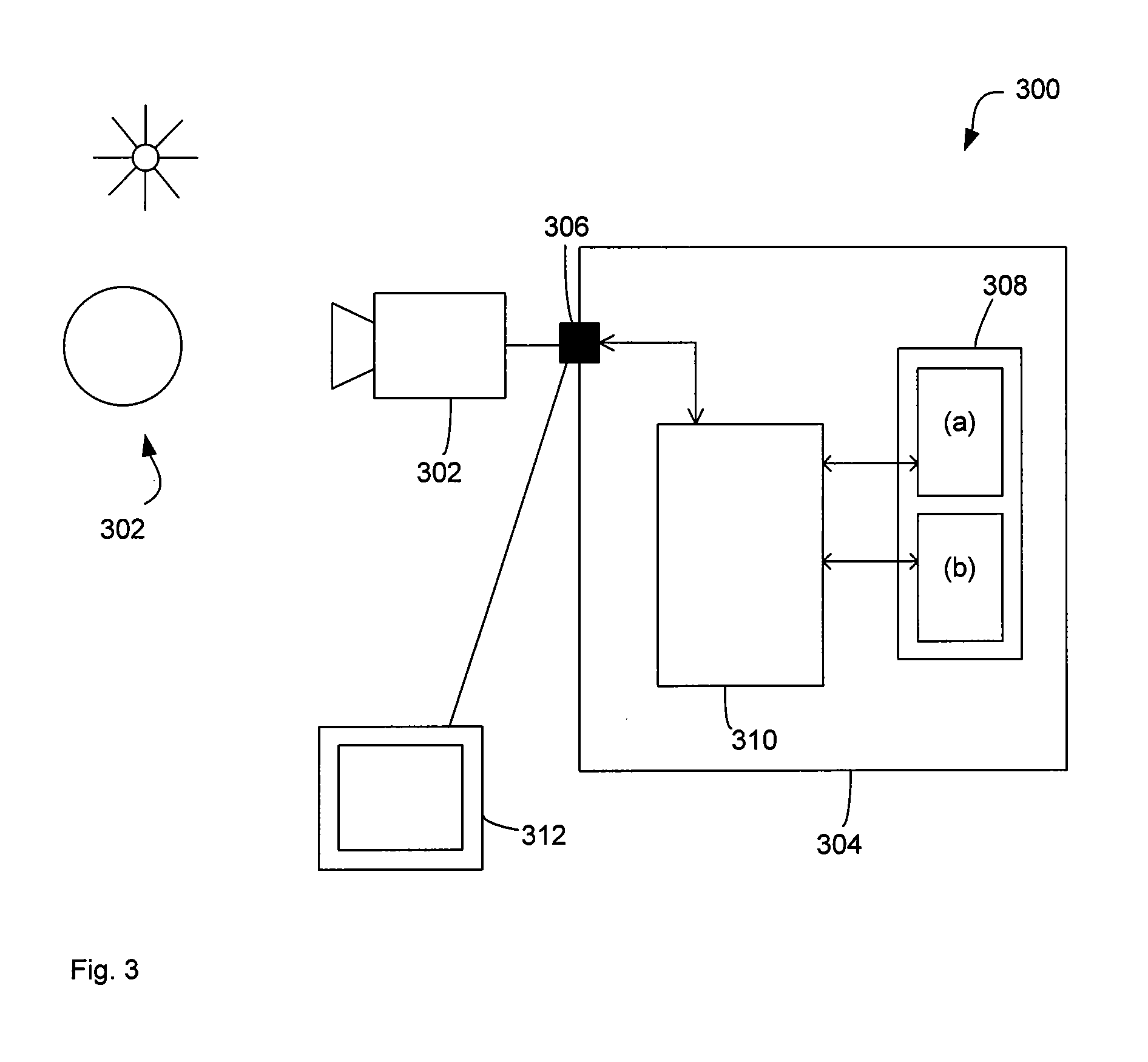
[0077]FIG. 3 illustrates a computer system 300 for determining basis spectra, that is underlying independent spectra, of wavelength indexed image data and decomposing the image data into the underlying spectra. Computer system 300 comprises a sensor 302 and a computer 304. In this example the sensor 302 is a hyperspectral or multispectral sensor that is able to capture an image of a scene 305, in this case the earth illuminated by the sun.

[0078]In one example, the computer system is integrated into a satellite orbiting the sun. In other examples the computer system is integrated into a handheld device such as a consumer camera and the scene 302 may be any scene on the earth, such as a tourist attraction or a person. The scene may also be illuminated by multiple artificial light sources, such as fluorescent lamps. The sensor 302 may have a number of bands that balances computational costs with accuracy. The sensor 302 may have as low as four bands and as high as hundreds.

[0079]The co...


PUM


Abstract

The disclosure concerns processing of electronic images, such as hyperspectral or multispectral images. In particular, but is not limited to methods, software and computer systems for determining underlying spectra of an image of a scene. The image data comprises for each pixel location a sampled image spectrum that is a mixture of plural reflectance spectra. Processor 310 determines or accesses plural hyperplanes that each have plural linearly independent basis vectors. Each hyperplane represents an estimate of one of the plural reflectance spectra. The processor 310 then determines for each pixel location, a contribution of the plural basis vectors of each hyperplane to the image spectrum of that pixel location. The processor 310 determines or accesses plural hyperplanes and not plural endmembers directly. Hyperplanes are two-dimensional while endmembers are only one-dimensional. As a result, hyperplanes carry more information, such as the illumination spectrum and are therefore of greater use. The decomposition of the image data into hyperplanes is possible without knowing the illumination spectrum. This decomposition allows for a range of new applications such as endmember extraction and compact representation.

Description

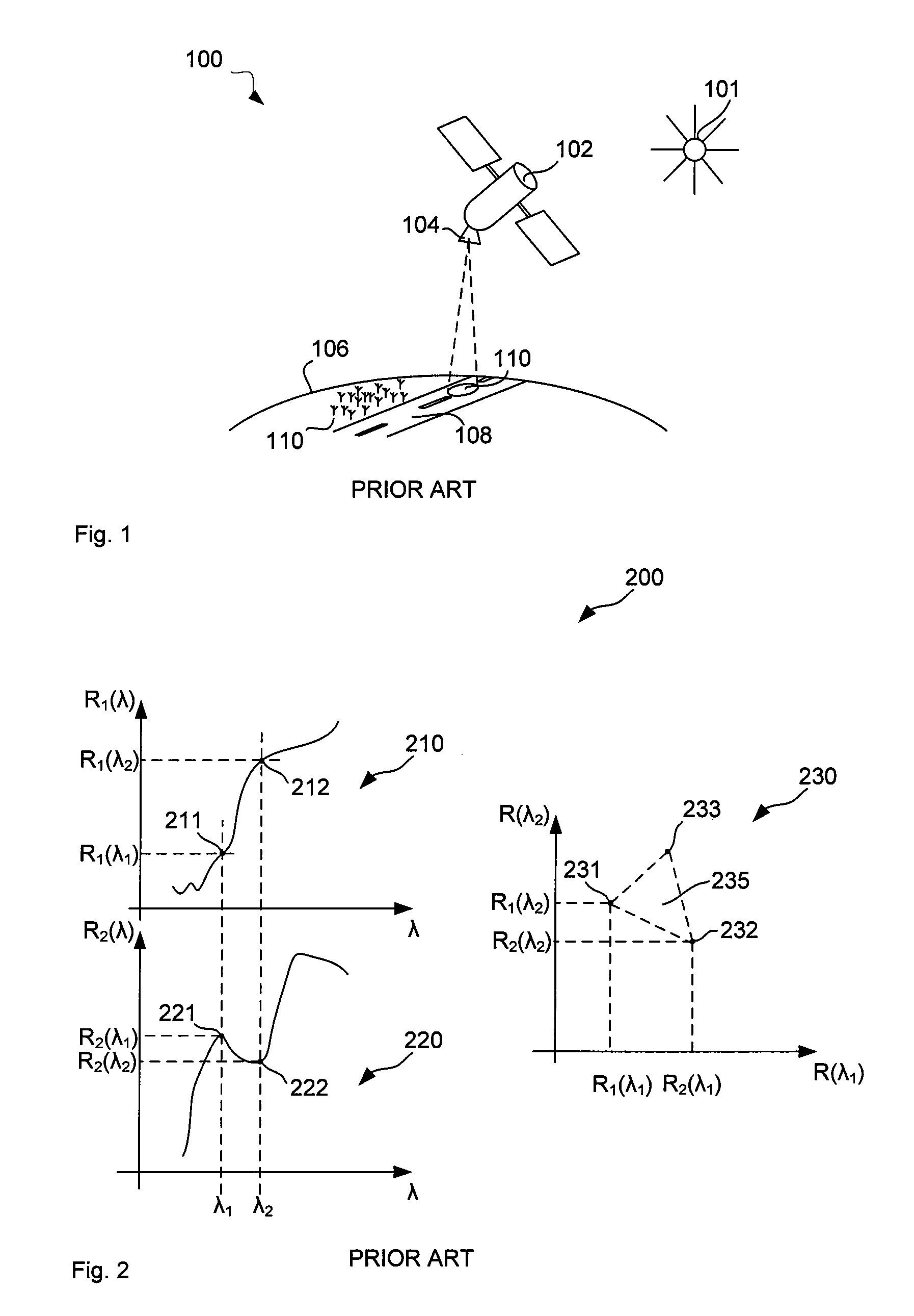
TECHNICAL FIELD[0001]The disclosure concerns processing of electronic images, such as hyperspectral or multispectral images. In particular the invention concerns, but is not limited to, methods, software and computer systems for determining underlying spectra of materials in a scene captured in the image.BACKGROUND ART[0002]Aerial surveillance is commonly used for investigating the surface of the earth. In particular, images taken by satellites are used to identify objects or materials on the ground.[0003]FIG. 1 illustrates a surveillance system 100 comprising an illumination source 101, such as the sun and a satellite 102 with a camera 104. The camera captures images of the surface of the earth 106. Located on the surface of the earth 106 are in this example a street 108 and plants 110. The street 108 and the plants 110 differ in the way they reflect the light which is the reason why they appear as having different colours to the eye. The measure of reflection of light from differe...

Claims


Application Information

Patent Timeline
IPC IPC(8): G06K9/46G06V20/13
CPCG06K9/0063G06V20/13
Inventor ROBLES-KELLY, ANTONIOHUYNH, CONG PHUOC
Owner NAT ICT AUSTRALIA
Learn More