Multimode optical fiber and optical backplane using multimode optical fiber

a multi-mode optical fiber and optical backplane technology, applied in the field of fiber optic communication, can solve problems such as the large overall diameter of fibers

Inactive Publication Date: 2013-02-14
CORNING INC
View PDF2 Cites 34 Cited by
  • Summary
  • Abstract
  • Description
  • Claims
  • Application Information

AI Technical Summary

Problems solved by technology

Multimode fiber optic cable offers a plurality of modes, but conventional multimode fibers generally require a relatively larger diameter core and thus generally result in larger overall diameter fibers.

Method used


Image

  • Multimode optical fiber and optical backplane using multimode optical fiber
  • Multimode optical fiber and optical backplane using multimode optical fiber
  • Multimode optical fiber and optical backplane using multimode optical fiber

Examples


examples

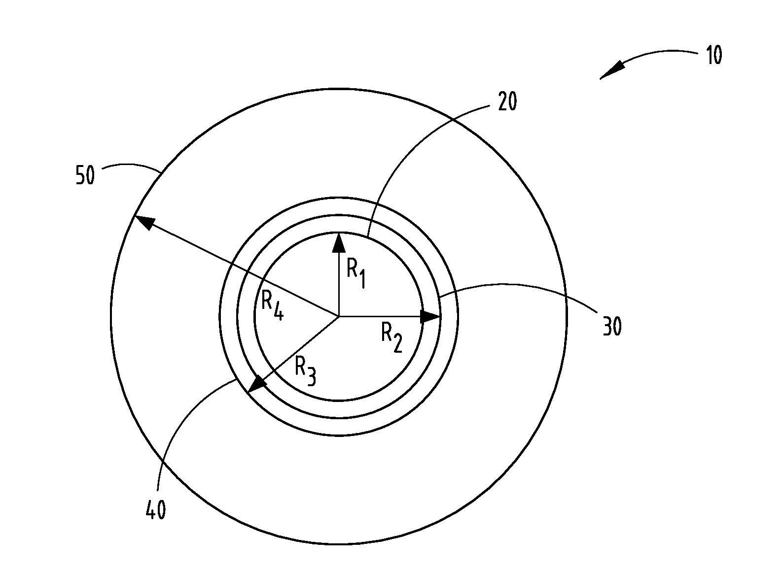
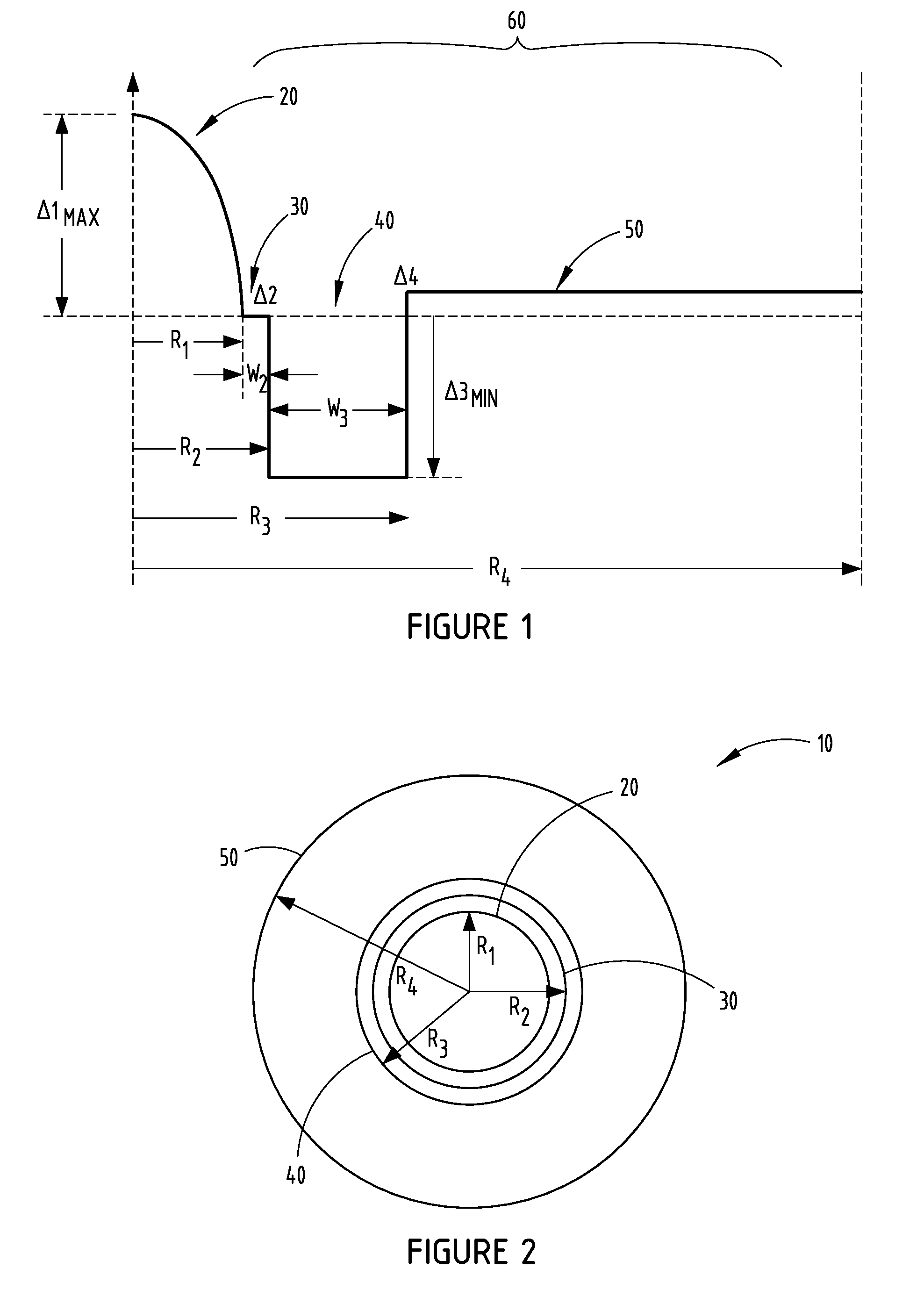
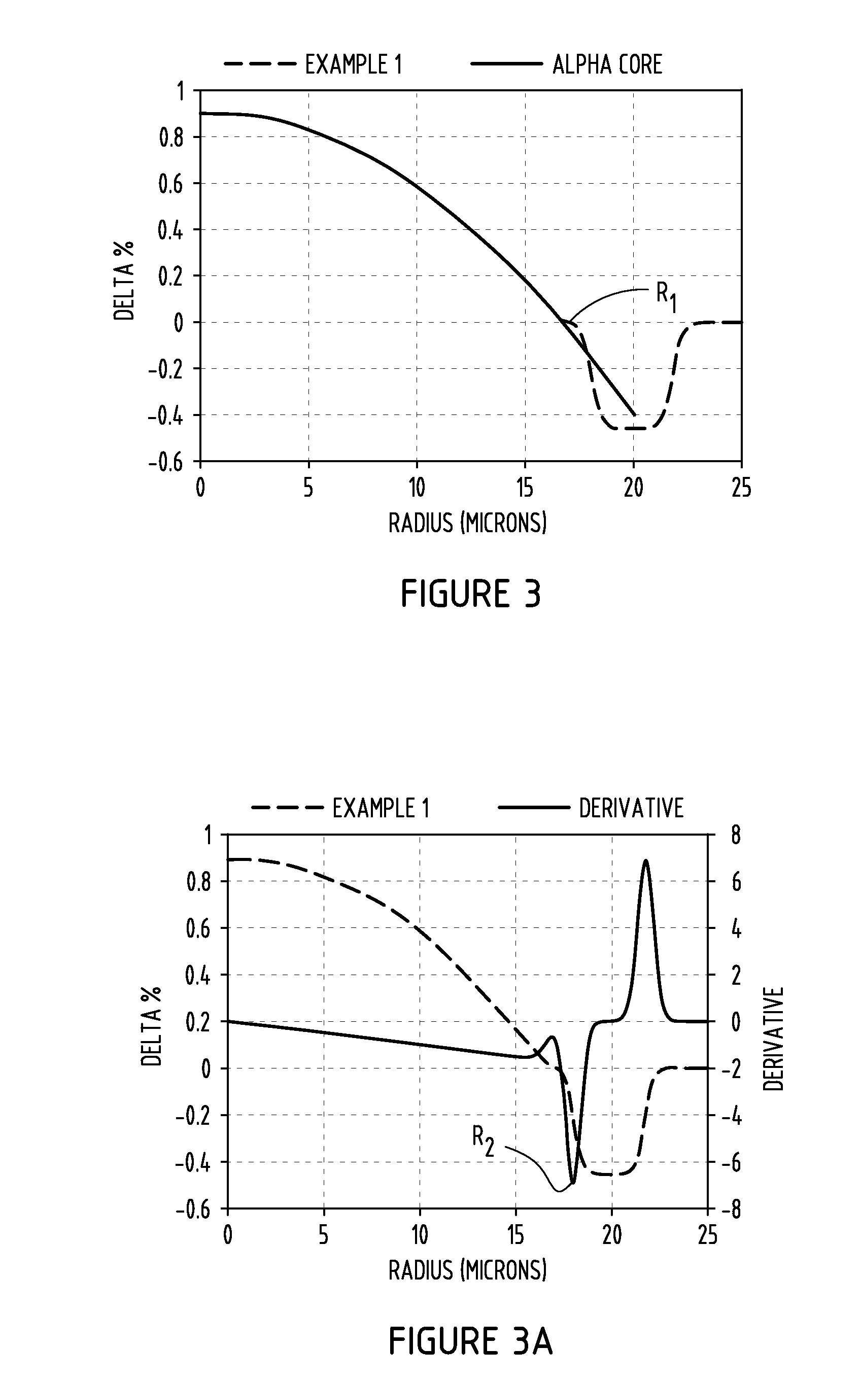
[0033]The tables 1-5 presented below summarize various examples generally arranged in five sets of embodiments of multimode fibers that were modeled having various characteristics in accordance with the embodiments disclosed herein and compared to a comparative fiber shown in FIG. 1. Various calculations of the parameters of the multi-mode fibers were calculated. These parameters include the relative refractive index of the core relative refractive index ΔiMAX of the core, outer core radius R1, and the graded index alpha (α) parameter. Additionally, the parameters include the inner cladding relative refractive index Δ2, the inner cladding maximum relative refractive index Δ2MAX, the outer radius of the inner annular portion of the cladding R2, and the width W2 of the inner annular portion 40. Further, the parameters include the minimum relative refractive index Δ3MIN of the depressed-index annular portion 50, and the outer radius R3 of the depressed-index annular portion 50. Further...


PUM


Abstract

An optical backplane system is provided. The optical backplane system includes at least one transceiver, at least one optical connector, and a plurality of multimode optical fibers coupled to the at least one optical connector. Each multimode optical fiber includes a graded index glass core having a diameter in the range of 24 microns to 40 microns, a graded index having an alpha less than 2.12 and a maximum relative refractive index in the range between 0.6 percent and 1.9 percent. The optical backplane further includes a cladding surrounding and in contact with the core. The cladding includes a depressed-index annular portion. The fiber has an overfilled bandwidth greater than 2.0 GHz-km at 1310 nm.

Description

CROSS-REFERENCE TO RELATED APPLICATIONS[0001]This application claims the benefit of priority under 35 U.S.C. §119 of U.S. Provisional Application Ser. No. 61 / 522,278, filed on Aug. 11, 2011, the content of which is relied upon and incorporated herein by reference in its entirety.BACKGROUND[0002]The present invention generally relates to fiber optic communication, and more particularly relates to small diameter multimode optical fiber that may be particularly useful for use in an optical backplane.High performance computing and server installations typically require a large number of processor-to-processor interconnections and utilize optical backplanes. Optical interconnects advantageously require much less electrical power than conventional wired systems and offer high speed data communication at long distances. Conventional fiber optic communication systems employ single mode or multimode optical fibers to transfer the data between remote locations. Multimode fiber optic cable off...

Claims


Application Information

Patent Timeline
Patent Type & Authority Applications(United States)
IPC IPC(8): G02B6/028
CPCG02B6/4202G02B6/43G02B6/0288G02B6/0365G02B6/03627G02B6/0281
Inventor BICKHAM, SCOTT ROBERTSONBERKEY, GEORGE EDWARDKOROLEV, ANDREY EVGENIEVICHLI, MING-JUNLOBANOV, SERGEY A.
Owner CORNING INC
Why Eureka
Try Eureka