Method and tool for producing a component and a component produced by forming

a technology of component and lateral extrusion, which is applied in the field of method and tool for producing components and components produced by forming, can solve the problems of buckling of the thin wall of the preform, the dimension of the structure provided by the tool through the cavity and the material to be filled by the lateral extrusion process, and the production of considerable manufacturing effor

Active Publication Date: 2013-02-14
SCHULER CARTEC
View PDF16 Cites 19 Cited by
  • Summary
  • Abstract
  • Description
  • Claims
  • Application Information

AI Technical Summary

Benefits of technology

[0008]The object of the invention is therefore to provide a method and a device, with which a component can be produced from a thin-walled preform by forming, wherein buckling is avoided, even with a relatively large ratio of the height of the preform to the wall thickness thereof. A further object of the present invention is to develop a component produced by forming, the component being produced in accordance with the method according to the present invention and using a device according to the present invention.

Problems solved by technology

When considering the category of gearwheels by way of example, these often have to be produced with considerable manufacturing effort, for example by machining a solid body.
The approach described in DE 37 18 884 A1 is only applicable, however, to a limited number of preforms to be formed, since a considerable amount of pressure has to be exerted onto the component along the direction of compression to achieve the lateral extrusion process.
If, however, contrary to the teaching of DE 37 18 884 A1, a preform formed from a solid material is not inserted into the tool, but instead a thin-walled hollow body, for example, a tube portion or a beaker-shaped hollow body is to be formed, the dimension of the structure which is provided by the tool through the cavities and which is to be filled with material by the lateral extrusion process, is extremely limited.
The reason for this lies primarily in the fact that the larger the structure to be filled, the greater the risk of buckling of the thin wall of the preform in the region of the structure at the start of the forming process.
Otherwise, there is a risk of buckling, which has serious effects on the properties of the component produced.
The disadvantage of this method lies in the use of a hollow body as a preform, which is merely to be used for the production of a structure of limited dimension and, in addition, cannot produce a precisely defined geometry with the plastic support body.
In this case, too, the disadvantage is the production of a structure (spoke flange) of limited dimension due to the use of a hollow body as a preliminary workpiece (preform) without use of a support element.

Method used


Image

  • Method and tool for producing a component and a component produced by forming
  • Method and tool for producing a component and a component produced by forming
  • Method and tool for producing a component and a component produced by forming

Examples


Embodiment Construction

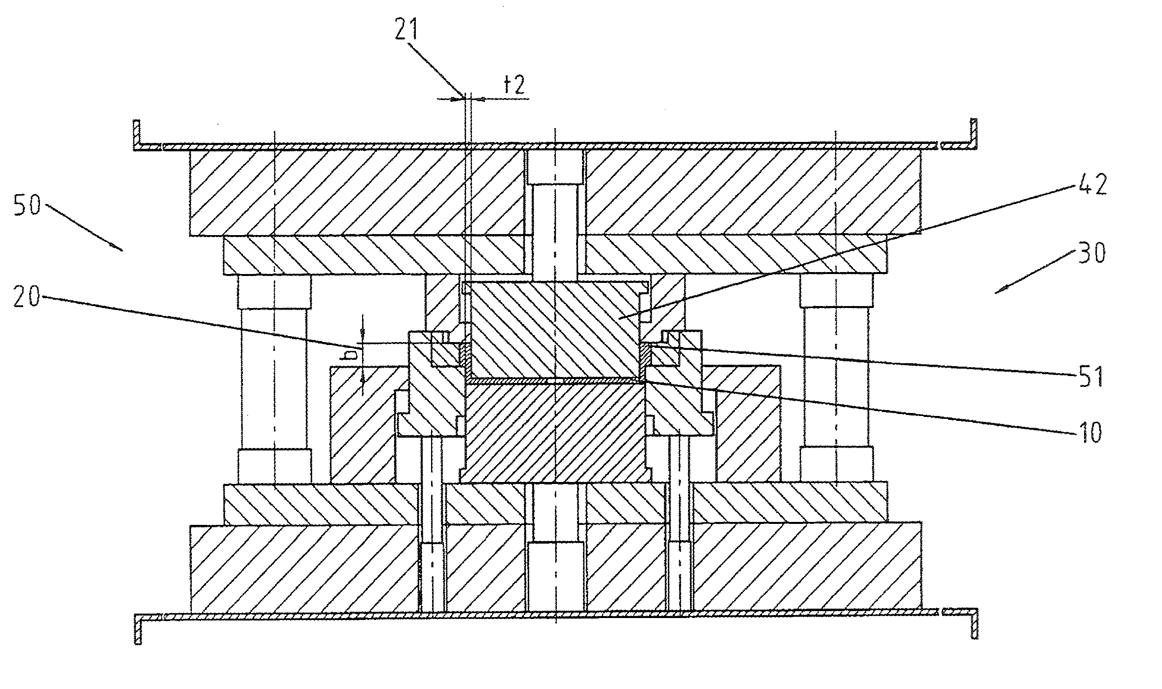
[0064]The figures will be explained in greater detail hereinafter. Recurring components in individual illustrations shown in different method states according to the invention during operation of an installation or forming installation are of course to be considered as being denoted for all illustrated figures, without this being stated explicitly for each individual illustration. Within the context of the present invention, an installation is to be understood to mean a forming device in which the tool according to the present invention is used and which carries out the method according to the present invention. The mechanical means used to carry out the method are not relevant to the consideration of the present invention.

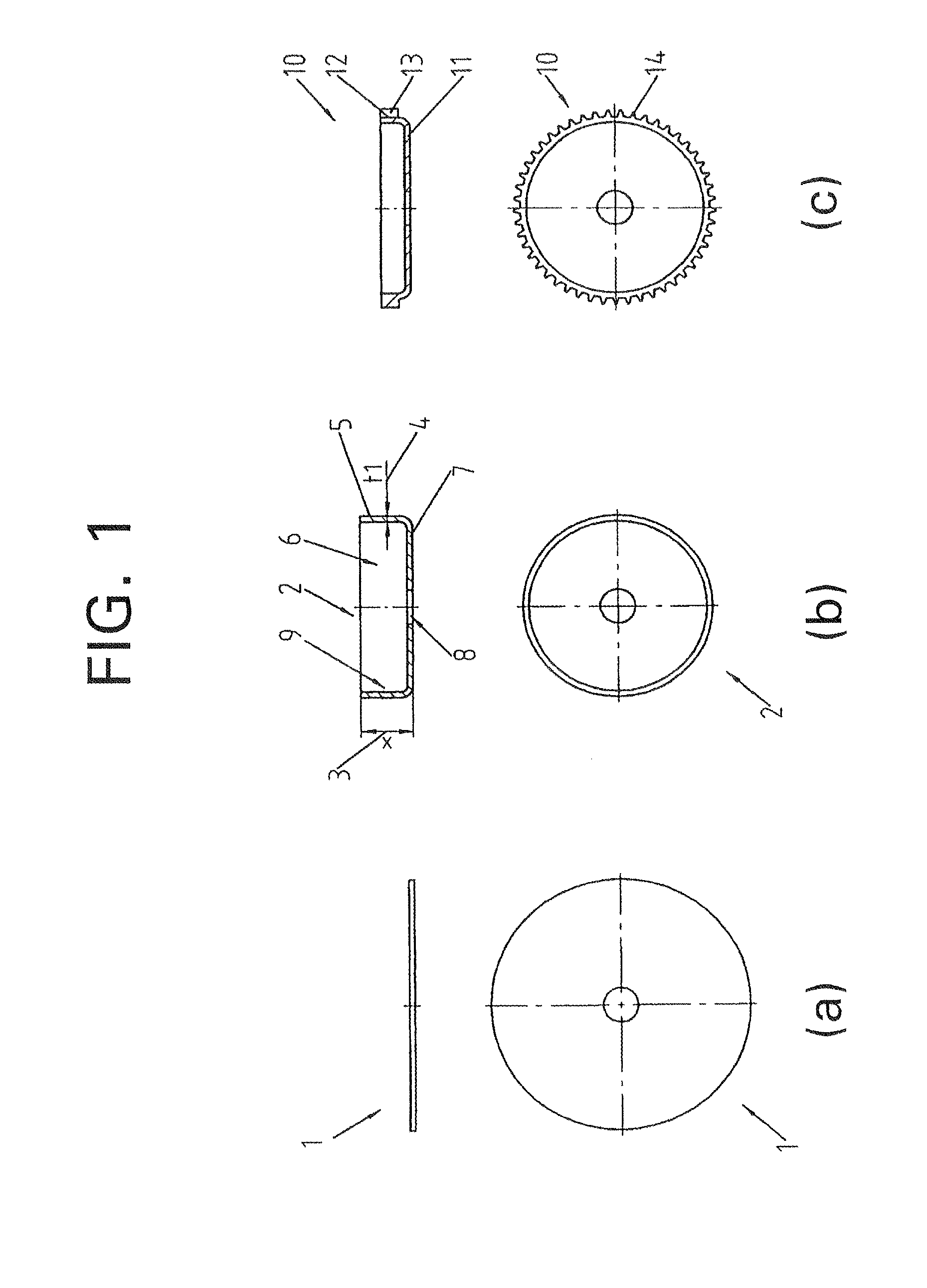
[0065]Specifically, FIG. 1(a) shows a planar blank 1, preferably formed from a sheet metal, which is formed into a preform 2, which is then introduced into the method according to the present invention. The illustrations according to FIGS. 1(a)-(c) are shown in se...


PUM

PropertyMeasurementUnit
temperatureaaaaaaaaaa
thickness t1aaaaaaaaaa
forming forceaaaaaaaaaa

Abstract

The invention relates to a component, a method, and a tool for forming, in particular for the lateral extrusion or upsetting of thin-walled preforms to form components having a structure formed thereon, in particular having a toothing, wherein, by carrying out the method according to the invention and by using the tool according to the invention, buckling of the wall of the preform during the forming process to form the component according to the invention is prevented.

Description

CROSS REFERENCE TO RELATED APPLICATIONS[0001]This application is a continuation of International Application No. PCT / EP2011 / 000783 filed Feb. 18, 2011, which designated the United States, and claims the benefit under 35 USC §119(a)-(d) of German Application No. 10 2010 009 345.9 filed Feb. 25, 2010, the entireties of which are incorporated herein by reference.FIELD OF THE INVENTION[0002]The application relates to a method for producing a component from a metal material, a tool for producing a component by forming, and a mechanical component produced by forming.BACKGROUND OF THE INVENTION[0003]The possibilities for use of mechanical components, in particular mechanical gearwheels, in the field of mechanical engineering are practically endless. When considering the category of gearwheels by way of example, these often have to be produced with considerable manufacturing effort, for example by machining a solid body.[0004]An alternative to machining is provided by the possibility of for...

Claims


Application Information

Patent Timeline
Patent Type & Authority Applications(United States)
IPC IPC(8): B21D22/20B32B1/00
CPCB21J5/08B21J9/06Y10T428/1241B21K21/12B21K1/30
Inventor GERLACH, LARSWERBS, MICHAELBAWOHL, ANDREASGEISINGER, KARL
Owner SCHULER CARTEC
Why Eureka
Try Eureka