U-Channel Coaxial F-Connector

a coaxial f-connector and u-channel technology, applied in the direction of coupling device connection, contact member manufacturing, coupling/disconnecting parts, etc., can solve problems such as adversely affecting the signal

Inactive Publication Date: 2013-02-14
GENESIS TECH USA
View PDF6 Cites 246 Cited by
  • Summary
  • Abstract
  • Description
  • Claims
  • Application Information

AI Technical Summary

Benefits of technology

[0010]This Summary is provided to introduce a selection of concepts in a simplified form that are further described below in the Detailed Description. This Summary is not intended to identify key features or essential features of the claimed subject

Problems solved by technology

It is important that coaxial cable be terminated properly, i.e., that the connectors at the end of the coa

Method used


Image

  • U-Channel Coaxial F-Connector
  • U-Channel Coaxial F-Connector
  • U-Channel Coaxial F-Connector

Examples


Embodiment Construction

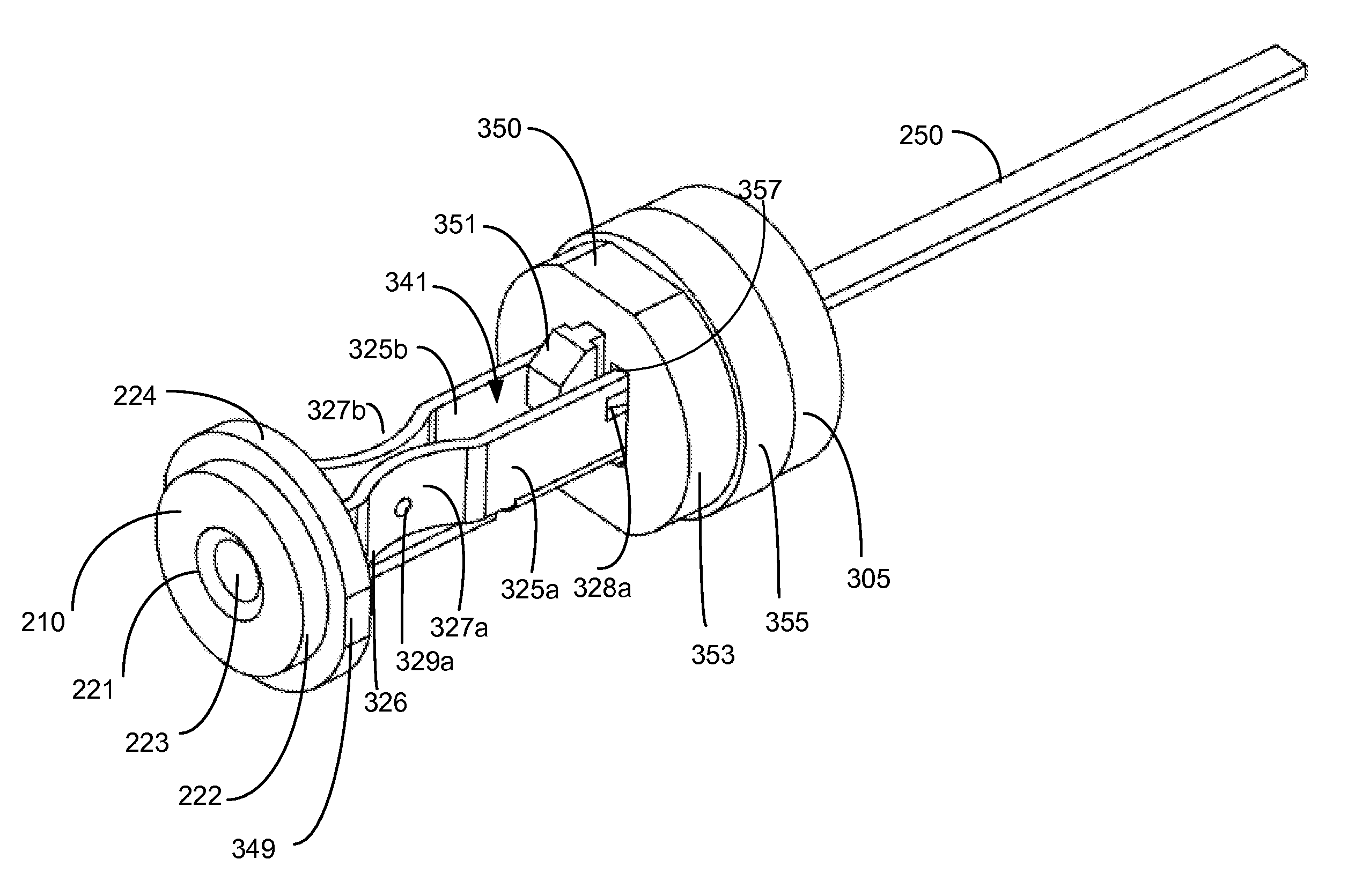
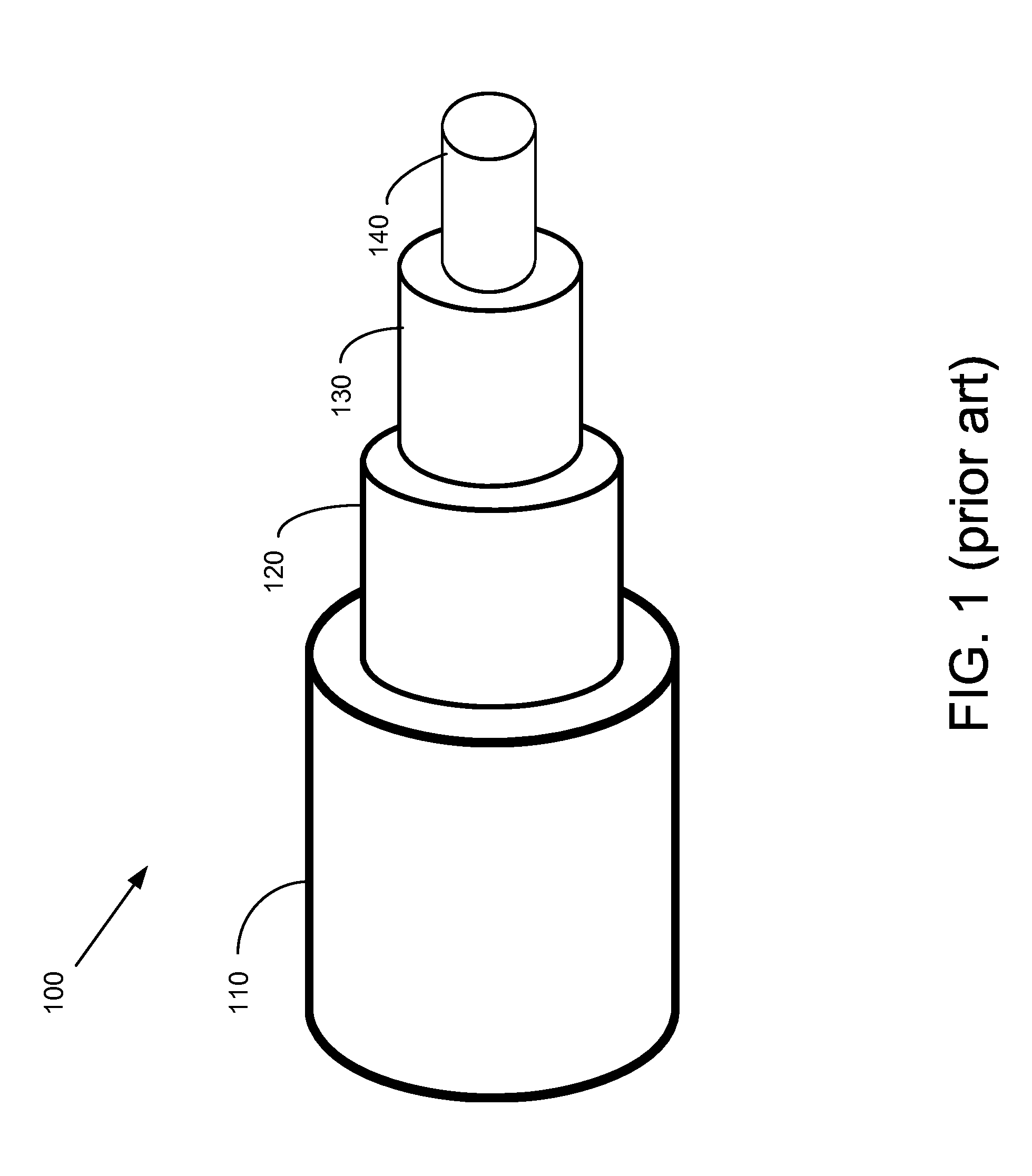
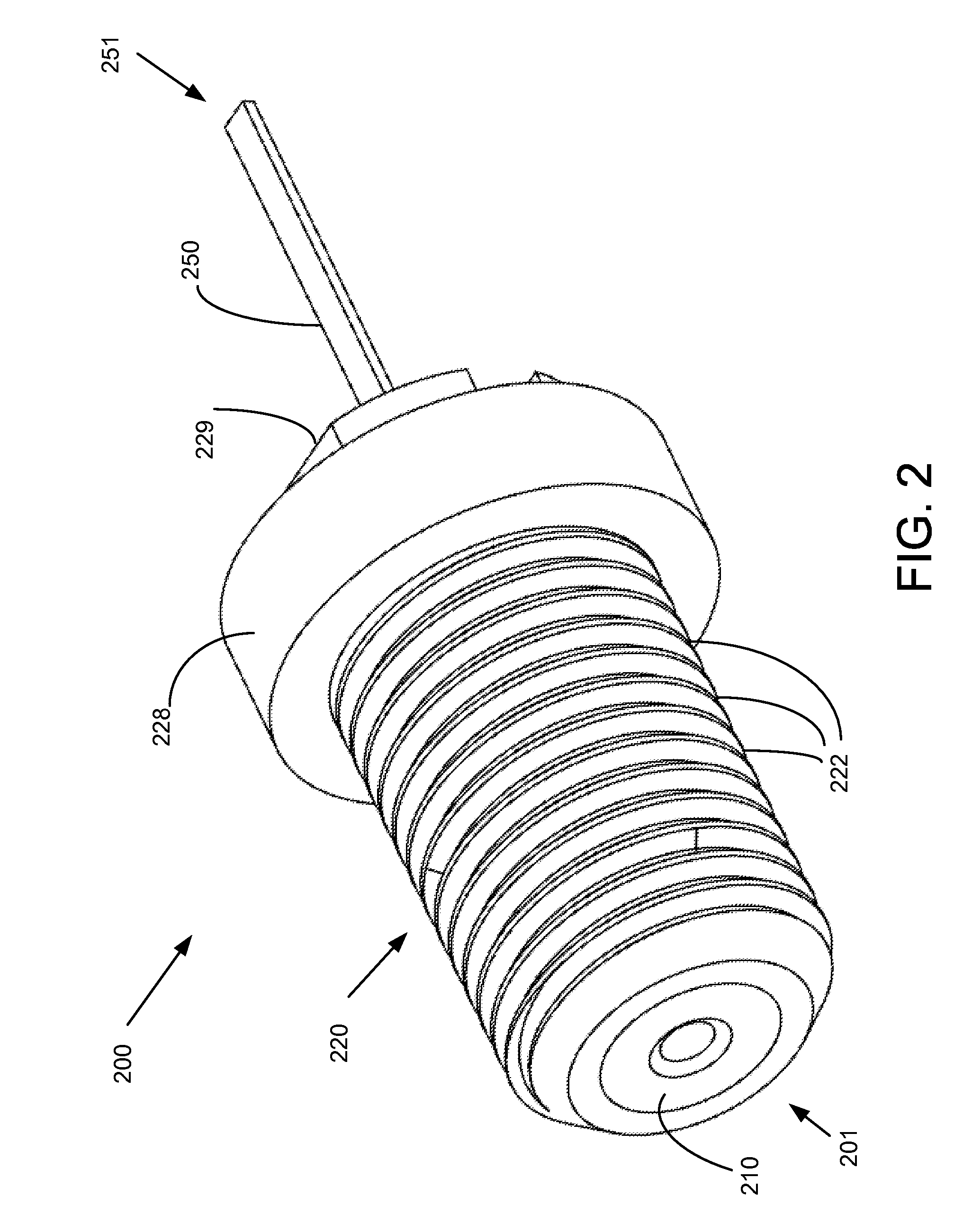
[0020]The following detailed description is directed to a coaxial cable connector. Coaxial cable is frequently used in delivery of video signals, and consumers frequently encounter coaxial cable in conjunction with residential cable television service applications. Coaxial cable is typically used to provide video signals to a set top box or a television set by a cable service company.

[0021]In the following detailed description, references are made to the accompanying drawings that form a part hereof, and which are shown by way of illustration specific embodiments or examples. Referring now to the drawings, in which like numerals represent like elements throughout the several figures, aspects of a coaxial F-connector be presented. In general, the F-connector has several structures that are symmetrical about an axis. A particular instance of a symmetrical structure is denoted by a suffix letter (e.g., “325a” or “325b”). Reference to a symmetrical structure element without the suffix l...


PUM

PropertyMeasurementUnit
Massaaaaaaaaaa
Massaaaaaaaaaa
Electric impedanceaaaaaaaaaa

Abstract

An F-connector for a coaxial cable comprises a front insulator, a back insulator, a connecting lead, and a locking ring. The connecting lead has an interior portion and an exterior portion. The interior portion is configured with a pair of side wall portions which are parallel to each other, and which together with a bottom portion form a U-shaped channel. The side wall portions each comprise a curved portion that are configured to grip the center conductor of the coaxial cable so as to withstand a certain level of withdrawal force, and such that the F-connector exhibits a desired impedance of 75 Ohms. The connecting lead engages with the front insulator and the back insulator such that the components are held in position within a connector body.

Description

BACKGROUND[0001]Coaxial cable is frequently encountered by consumers as the cable used for radio frequency (“RF”) transmissions, particularly for conventional analog and digital video signals. More specifically, coaxial cable is typically used by cable television service providers to provide video signals to residential service locations. It can be used for other applications, including data communications involving local area networks. The structure of coaxial cable provides protection of the signal from external electromagnetic interference and largely contains the signal within the cable itself.[0002]A common embodiment of coaxial cable comprises a center conductor (usually a solid copper wire) surrounded by an insulating layer that is enclosed by a shield layer, typically a woven metallic braid. Finally, an outer insulating jacket provides protection. Normally, the shield is kept at ground potential and a voltage is applied to the center conductor (with respect to ground) to car...

Claims


Application Information

Patent Timeline
IPC IPC(8): H01R13/622H01R43/16H01R9/05
CPCH01R9/05Y10T29/49208H01R13/111
Inventor VALLELY, WILLIAM GRAYDAUGHTRY, JR., EARL ANTHONYHODGE, RONALD
Owner GENESIS TECH USA
Why Eureka
Try Eureka