Physical quantity sensor and electronic apparatus

Active Publication Date: 2013-02-21
SEIKO EPSON CORP
View PDF14 Cites 12 Cited by
  • Summary
  • Abstract
  • Description
  • Claims
  • Application Information

AI Technical Summary

Benefits of technology

[0028]Accordingly, the electronic apparatus having the configuration includes the physical quantity sensor according to any one of the appl

Problems solved by technology

Thereby, in the physical quantity sensor, the increased parasitic capacitance is added to the detected original electrostatic capacitance, and thus, detection characteristics such as detection accuracy as a capacitance change detection type physical quantity sensor may be deteriorated.
As a result,

Method used


Image

  • Physical quantity sensor and electronic apparatus
  • Physical quantity sensor and electronic apparatus
  • Physical quantity sensor and electronic apparatus

Examples


Example

[0040]As below, an embodiment implementing the invention will be explained with reference to the drawings.

EMBODIMENT

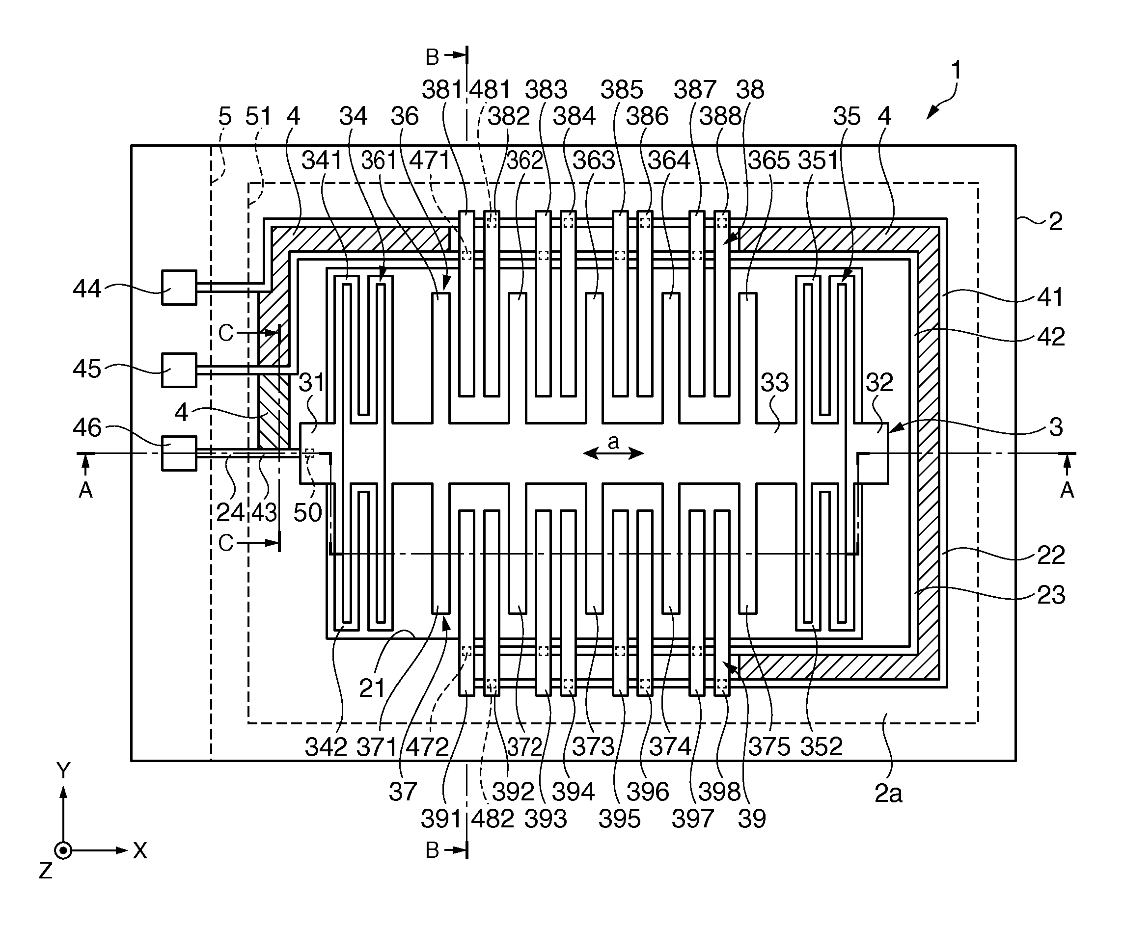
[0041]First, a configuration of a physical quantity sensor of a capacitance change detection type that detects physical quantities such as acceleration and angular velocities, for example, according to the embodiment will be explained.

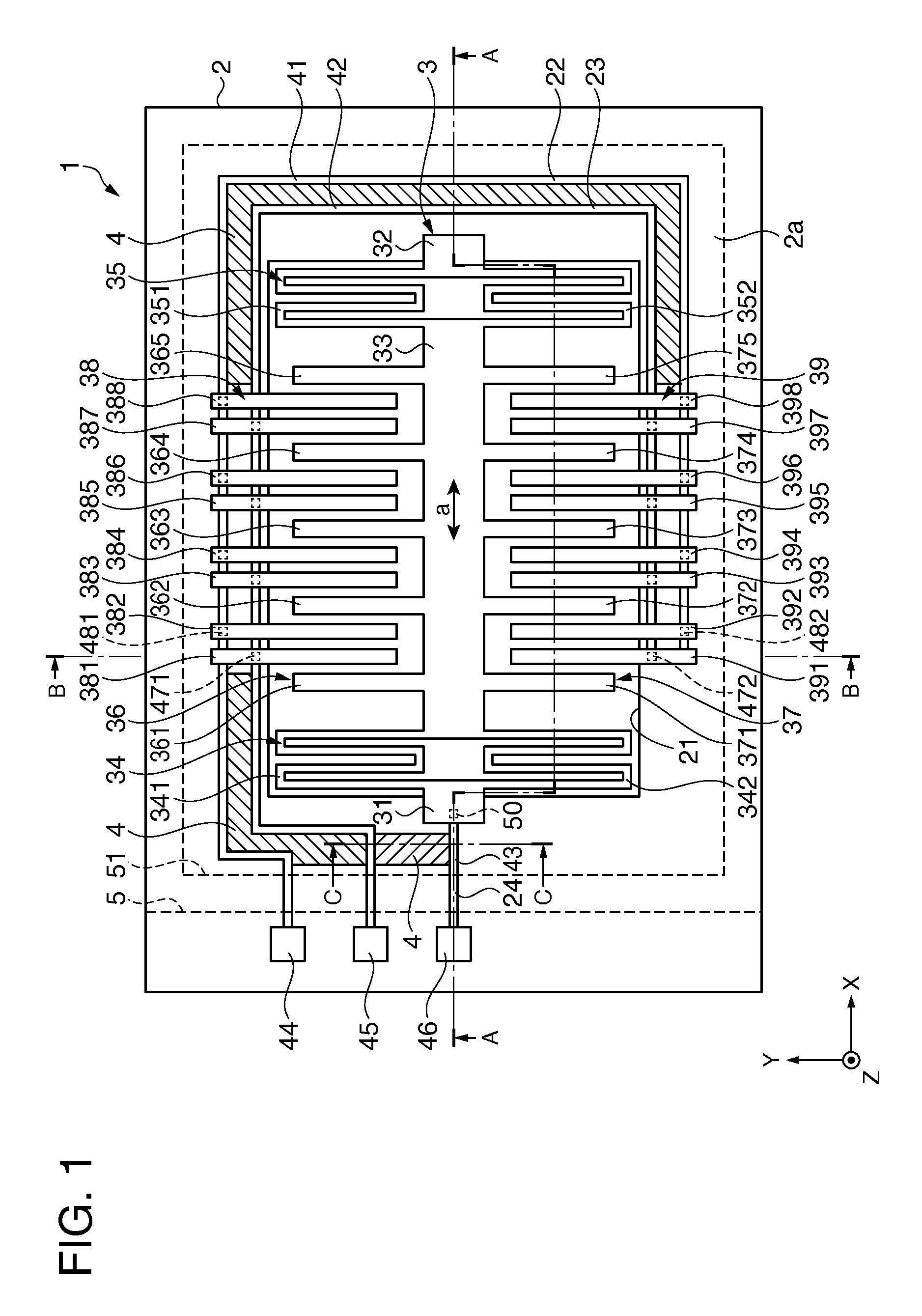
[0042]FIG. 1 is a schematic plan view showing a general configuration of a physical quantity sensor of the embodiment,

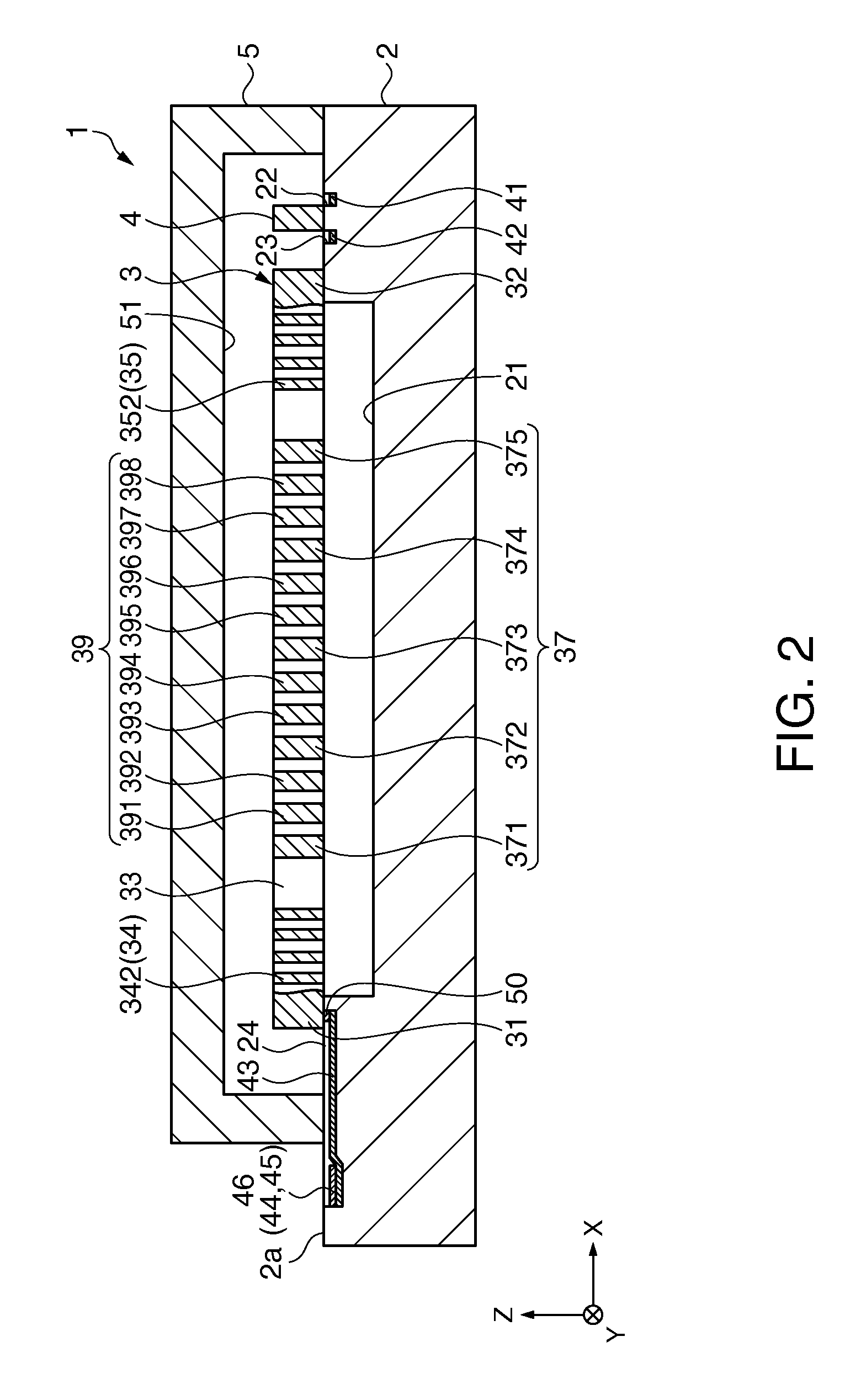
[0043]FIG. 2 is a schematic sectional view along A-A line in FIG. 1, FIG. 3 is a schematic sectional view along B-B line in FIG. 1, and FIG. 4 is a schematic sectional view of a main part along C-C line in FIG. 1.

[0044]For convenience of explanation, the dimension ratios of the respective component elements are different from actual dimension ratios. Further, in FIG. 1, a lid member is shown by a broken line.

[0045]As below, for convenience of explanation, the front side of the paper in FIG. 1 is referred to as “up”, the de...


PUM


Abstract

A physical quantity sensor includes a base substrate, a movable part located on the base substrate and provided on a principal surface of the base substrate, a movable electrode part provided in the movable part, and a fixed electrode part provided on the principal surface of the base substrate and located to be opposed to a movable electrode finger, and the fixed electrode part is connected to fixed electrode wiring provided at the principal surface side of the base substrate, the movable electrode part is connected to movable electrode wiring provided at the principal surface side of the base substrate, and a shield part is provided between the fixed electrode wiring and the movable electrode wiring.

Description

BACKGROUND[0001]1. Technical Field[0002]The present invention relates to a physical quantity sensor and an electronic apparatus including the physical quantity sensor.[0003]2. Related Art[0004]In related art, as a physical quantity sensor, a semiconductor dynamic quantity sensor (hereinafter, referred to as “physical quantity sensor”) including a base plate part sectioned by a cavity formed in a semiconductor substrate to extend in a lateral direction and located under the cavity, a frame part sectioned by a groove formed in the cavity and the semiconductor substrate to extend in a longitudinal direction and located at the side of the cavity and the groove, abeam structure sectioned by the cavity and the groove, located on the cavity, extending from the frame part, and having a movable electrode that is displaced in response to a dynamic quantity (for example, acceleration), a fixed electrode sectioned by the cavity and the groove, located on the cavity, extending from the frame par...

Claims


Application Information

Patent Timeline
IPC IPC(8): G01P15/00
CPCG01P15/0802G01P2015/0814G01P15/125
Inventor YODA, MITSUHIRO
Owner SEIKO EPSON CORP
Why Eureka
Try Eureka