Pipe Joint Gasket and Method of Using Same

Active Publication Date: 2013-02-21
MCWANE
View PDF2 Cites 17 Cited by
  • Summary
  • Abstract
  • Description
  • Claims
  • Application Information

AI Technical Summary

Benefits of technology

[0010]Specifically, as the retainer bead is sheared or deformed, the segment discontinues rotation about the bead and translates or shifts toward the front wall of the bell end until the single tooth of the metal segment engages the front wall. Upon engagement of the single tooth with the front wall of the bell end, a second load path is created through the segment and between the axial surface of the spigot and a radial surface of the bell, i.e., front wall. The second load path has an angle relative to the spigot that is substantially less t

Problems solved by technology

In the event the radial load component becomes too large, the spigot or bell ends can fail and fracture.
In other words, once the axial thrust force reaches a certain threshold upon fluid over-pressurization, rather than supporting the over-rotation

Method used


Image

  • Pipe Joint Gasket and Method of Using Same
  • Pipe Joint Gasket and Method of Using Same
  • Pipe Joint Gasket and Method of Using Same

Examples


Embodiment Construction

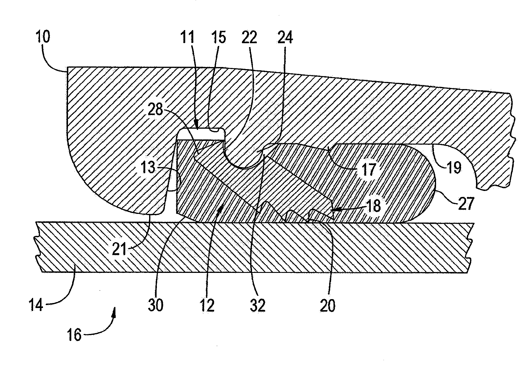
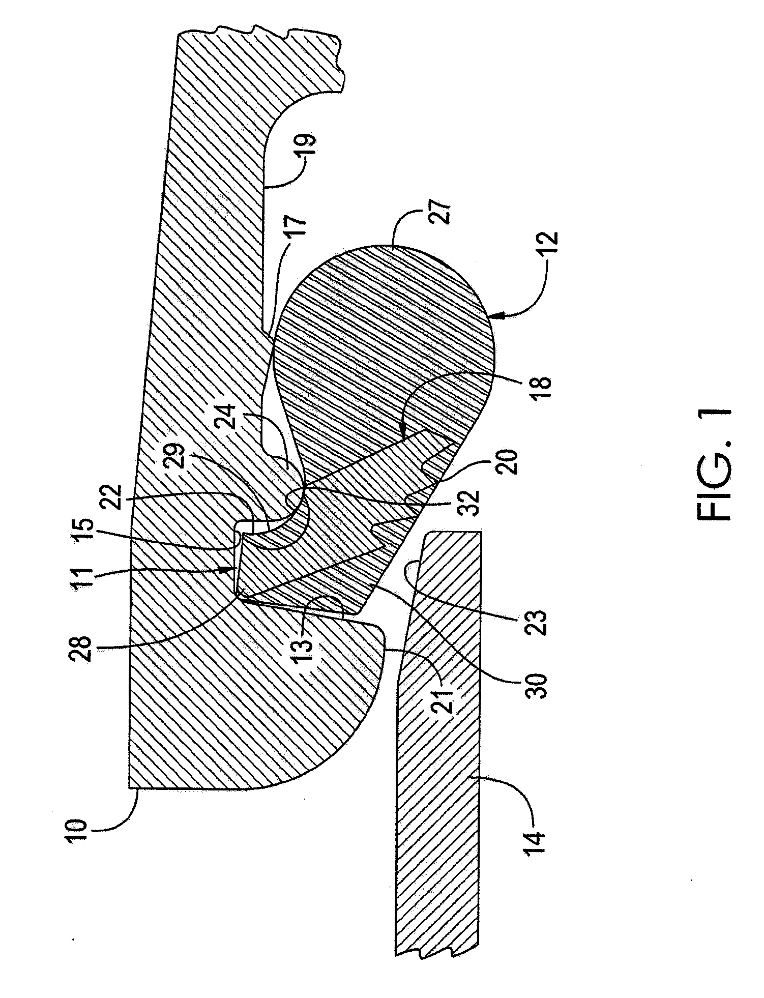
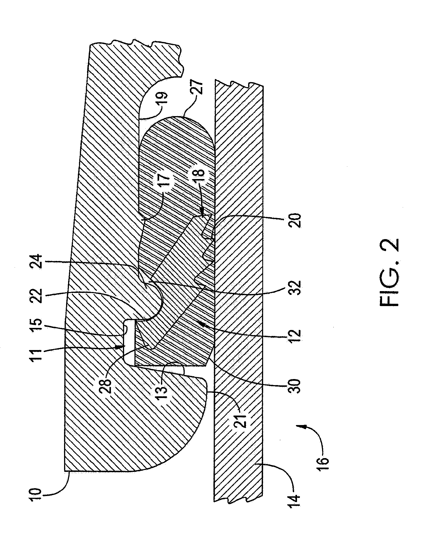
[0017]FIGS. 1 through 5 depict a fragmented cross-sectional view of a bell end 10 of one pipe using a gasket 12 of the present invention, a spigot end 14 of another pipe entering the pipe bell and the operation of gasket 12 upon the fluid pressurization and over-pressurization of a pipe joint 16 created between bell end 10 and spigot end 14. In particular, these figures illustrate the arrangement and operation of metal segments 18 in gasket 12 relative to bell end 10 and spigot end 14 during the formation, fluid pressurizing and fluid over-pressurization of joint 16. FIG. 5 is provided to show the circumferential arrangement and spacing of metal segments 18 throughout gasket 12.

[0018]Generally, gasket 12 is arranged for inhibiting leakage about joint 16 between the inside walls of bell end 10 and the outside wall of spigot end 14. More particularly, as illustrated in FIGS. 1 and 2, the inner surface of bell end 10 includes a retainer groove 11 bounded by a radially extending front w...


PUM

PropertyMeasurementUnit
Lengthaaaaaaaaaa
Angleaaaaaaaaaa
Angleaaaaaaaaaa

Abstract

A gasket for preventing separation of interconnected pipes without damaging the pipes. The gasket includes a compressible body having a plurality of metal segments partially embedded therein. Each of the metal segments includes a row of exposed teeth configured for engaging a spigot end of a pipe and a trough configured for pivotably engaging a bead on a bell. The trough is further configured for shearing or deforming the bead and inhibiting over-pivoting of the segment about the bead when the pipes are partially withdrawn away from one another, for example, during over-pressurization of the pipes.

Description

RELATED APPLICATIONS[0001]This application is a divisional of U.S. nonprovisional patent application Ser. No. 12 / 901,261, filed on Oct. 8, 2010 and titled, PIPE JOINT GASKET AND METHOD OF USING SAME, the entire contents of which are incorporated herein by reference.FIELD OF THE INVENTION[0002]The present invention is directed to a pipe joint gasket and more particularly to a pipe joint gasket including an arrangement of metal segments configured for preventing the separation and fracturing of interconnected, telescoping pipes during fluid over-pressurization.BACKGROUND OF THE INVENTION[0003]Pipe joint gaskets including anti-slip segments for preventing the separation of interconnected, telescoping pipes in applications where a fluid such as water for fire mains is held under high pressure are known in the art. Exemplary gaskets are described in U.S. Pat. Nos. 5,295,697 and 5,464,228 in which a rubber gasket, serving as a fluid seal, includes toothed metal segments spaced uniformly a...

Claims


Application Information

Patent Timeline
IPC IPC(8): F16L17/02
CPCY10T29/49872F16L37/0845
Inventor COPELAND, DANIEL A.KEEL, MICHAEL C.
Owner MCWANE
Why Eureka
Try Eureka