Rotor and rotating electric machine equipped with the rotor

Active Publication Date: 2013-02-21
HITACHI ASTEMO LTD
View PDF2 Cites 7 Cited by
  • Summary
  • Abstract
  • Description
  • Claims
  • Application Information

AI Technical Summary

Benefits of technology

[0020]According to the present invention, the extent of stress concentration in the key of a rotor that transmits rotational torque to a

Problems solved by technology

While the rotor core and the rotating shaft member constituting a rotor in the related art are often fastened t

Method used


Image

  • Rotor and rotating electric machine equipped with the rotor
  • Rotor and rotating electric machine equipped with the rotor
  • Rotor and rotating electric machine equipped with the rotor

Examples


Example

[0044]The first embodiment of the rotating electric machine according to the present invention is now described.

[0045](Overall Rotating Electric Machine)

[0046]The rotating electric machine in the first embodiment of the present invention assures higher rotation speed, as detailed below. For this reason, it is ideal in applications in which it is used as a traveling motor for an electric vehicle. While the rotating electric machine according to the present invention may be adopted in a pure electric vehicle engaged in traveling operation exclusively on a rotating electric machine or in a hybrid-type electric vehicle driven both by an engine and a rotating electric machine, the following description is given by assuming that the present invention is adopted in a hybrid electric vehicle.

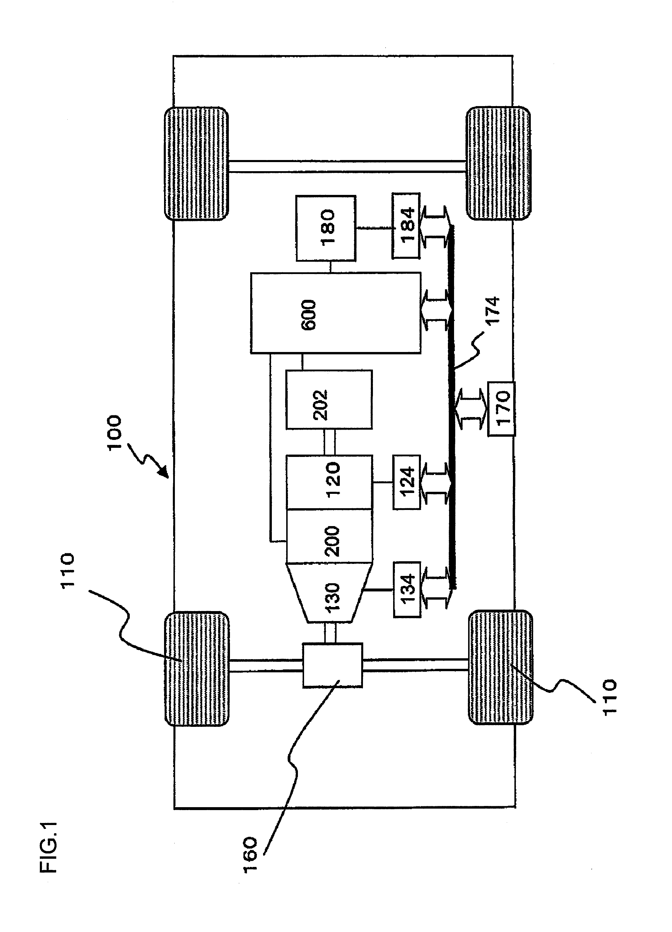
[0047]An engine 120, a first rotating electric machine 200, a second rotating electric machine 202 and a high-voltage battery 180 are mounted at a hybrid vehicle 100, as shown in FIG. 1.

[0048]The batter...

Example

Second Embodiment

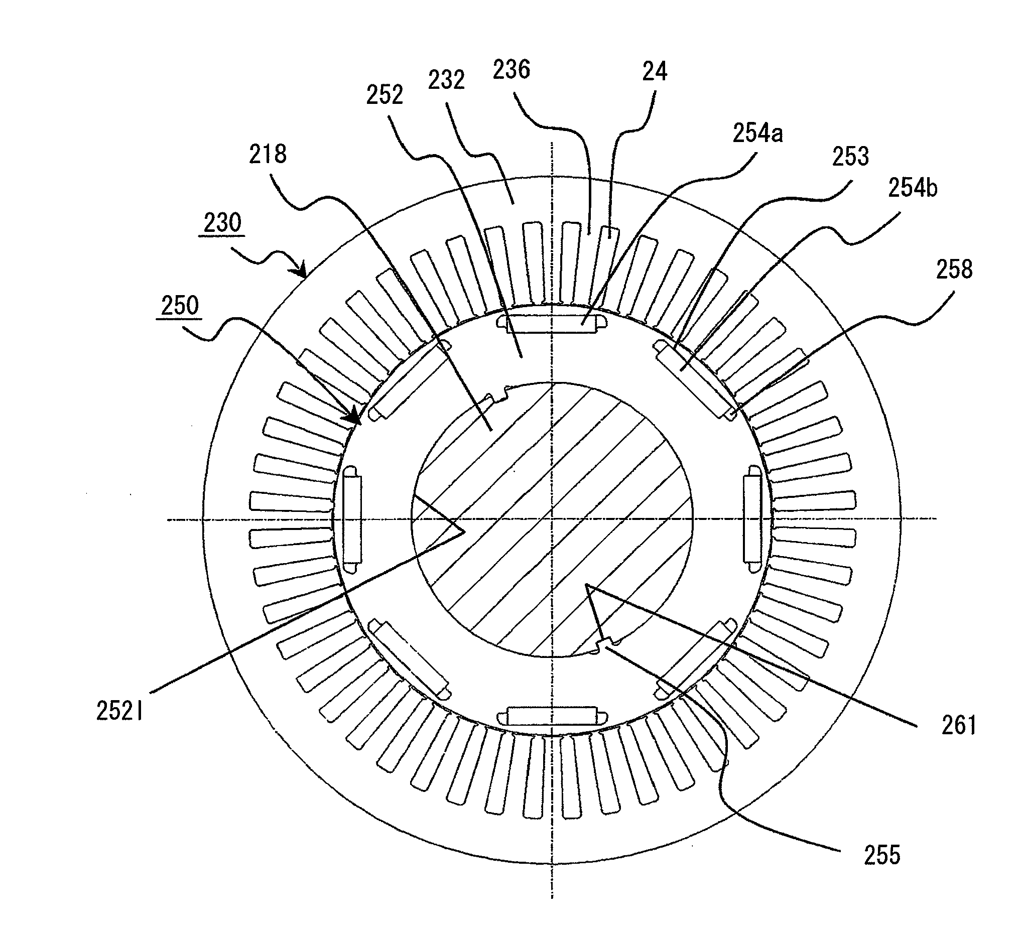
[0150]In reference to FIGS. 22 and 23, the second embodiment of the rotor and the rotating electric machine according to the present invention is described. In the second embodiment, a recessed circular arc contoured portion 410, recessed along the inner circumference, is fanned instead of the planar portion 400 in the first embodiment. It is to be noted that the same reference numerals are assigned to portions identical or equivalent to those in the first embodiment so as to preclude the necessity for a repeated explanations thereof.

[0151]As shown in FIG. 22, the recessed portions 256 are each formed with a key side surface 257 of the key 255, a circular arc contoured portion 410 formed with a circular arc having a relatively large radius R4, located at the bottom of the recessed portions 256, a connecting side surface 401 extending from the inner circumference 252I of the rotor core 252 toward the circular arc contoured portion 410, a first corner portion key1 ass...


PUM


Abstract

A rotor comprising: a rotating shaft with at least one keyway formed at an outer circumferential surface thereof and ranging along an axial direction; and a rotor core that includes a key that projects out on an inner circumferential side thereof, and is fitted in the keyway; wherein: a recessed portion that widens outward along a radial direction is formed at each of two sides of the key facing opposite each other along a circumferential direction at the rotor core; a planar portion is formed at a bottom area of the recessed portion so as to lessen stress occurring on each of the two sides of the key facing opposite each other along the circumferential direction; the planar portion is a straight contoured portion extending over a predetermined length along a direction perpendicular to a direction in which the key projects out, and a connecting side surface extending to an inner circumference of the rotor core is formed continuously to an end of the straight contoured portion located on a side opposite from a key side where a key is present; a first corner portion, connecting a side surface of the key with a key-side end of the straight contoured portion, is formed as a circular arc contoured portion; a second corner portion, connecting the end of the straight contoured portion, located on the side opposite from the key side, with the connecting side surface, is formed as a circular arc contoured portion; and dimensions and shapes of various portions are determined so as to substantially equalize stress levels in the first corner portion and in the second corner portion.

Description

TECHNICAL FIELD[0001]The present invention relates to a fastening structure that may be adopted when fastening a rotor of a rotating electric machine to a rotating shaft member.BACKGROUND ART[0002]A rotating electric machine used to drive a vehicle needs to rotate at a speed higher than the speed at which a standard rotating electric machine typically rotates in a different application and therefore, it is crucial that the rotor thereof achieve a sufficiently high level of strength. It is particularly important to assure a high level of strength over the area where the rotor core is fastened to the rotating shaft member. While the rotor core and the rotating shaft member constituting a rotor in the related art are often fastened together by using a clearance-fitted key, there is a concern that stress tends to concentrate readily at the key.[0003]This issue is addressed in patent literature 1, disclosing a rotor that includes a recessed part at the key, which assumes a shape achieved...

Claims


Application Information

Patent Timeline
IPC IPC(8): H02K1/28
CPCH02K1/28F16D1/0876
Inventor KAIMORI, TOMOAKINAKAYAMA, KENICHISAITO, YASUYUKIIKEDA, DAI
Owner HITACHI ASTEMO LTD
Why Eureka
Try Eureka