Electronic lock and method

a technology of electronic locks and locks, applied in the field of electronic locks, systems and methods, can solve problems such as the possibility of a security breach, the inability of the lock owner to establish a tedious routine, and the serious security flaw of the static access cod

Inactive Publication Date: 2013-02-21
GREISEN ENTERPRISES
View PDF8 Cites 101 Cited by
  • Summary
  • Abstract
  • Description
  • Claims
  • Application Information

AI Technical Summary

Benefits of technology

[0015]In still another embodiment having enhanced security, each valid argument further includes further data input into the human interface device, in addition to the input access code, each time an access code is input into the human interface device. The further data may for example be a realtor ID pertaining to a particular realtor who is authorized to receive access codes for the lock. In that example, the microcontroller may evaluate the hash function at valid arguments only if the additional input data equal the realtor ID, so that the microcontroller avoids wasting battery power performing hashes in response to input by unauthorized users.
[0017]In still another embodiment, caching may be used to minimize lock power usage. For example, rather than recalculating valid access codes each time an input access code is entered, the lock microcontroller may be further programmed with instructions to cache valid access codes, each time an input access code is received, to compare the input access code to any valid cached access codes, and if a match is found, unlock the mechanical locking mechanism. In a particular caching embodiment, the lock is further programmed with instructions to each time an argument becomes valid, hash automatically the newly valid argument to return the corresponding valid access code, and cache automatically the corresponding valid access code in a memory, and each time a valid access code becomes invalid, delete automatically the newly invalid access code from the memory. Each time an input access code is received, the microcontroller compares the input access code to any valid access codes cached in the memory, until a match is found between the input access code and one of the valid access codes cached in the memory, or until the input access code has been compared with all the valid access codes cached in the memory and no match has been found. If a match is found, the microcontroller unlocks the mechanical locking mechanism.
[0019]In yet another embodiment having enhanced flexibility, one or more static (i.e., not automatically changing) access codes may be stored in the lock memory. The lock is then further programmed with instructions to compare the input access code to any stored static access codes, and if the input access code equals any stored static access code, the microcontroller unlocks the mechanical locking mechanism.
[0024]In another embodiment of the system, the code server memory stores a plurality of hash functions and their respective correspondence to a plurality of electronic locks. The code server is further programmed with instructions to prompt a user to enter information identifying a lock, and, upon receiving information identifying one of the plurality of electronic locks, to determine the hash function corresponding to the identified lock, and to evaluate the hash function corresponding to the identified lock at the argument corresponding to the entered time period to return an access code valid for the identified lock during the entered time period. Each of the plurality of hash functions may be unique with respect to the rest of the plurality of hash functions, or the plurality of hash functions may include two or more identical hash functions. The former increases the security of any given lock, while the latter is useful wherever it would be useful for more than one traditional lock to have the same physical key, as in locks to multiple doors to the same residence or vehicle, for example.
[0026]In conjunction with the multiple-lock embodiment, the information identifying a particular lock may include a reset code provided to the lock owner upon purchase of the lock and a lock serial number. The code server memory stores in association with the lock identifying information a hash of a lock verification argument that includes at least the reset code, the lock serial number, and a security key stored in the code server, without the code server storing the reset code itself. This helps to keep the reset code secure. In such case, the code server is further programmed with instructions to prompt a user to input the reset code, to hash the lock verification argument to generate a lock verification hash, and to compare the lock verification hash with the stored hash. Then, only if the lock verification hash equals the stored hash, the code server proceeds to evaluate the hash function at the argument corresponding to the entered time period to generate the access code valid for the identified lock during the time period.

Problems solved by technology

However, static access codes have a serious security flaw in that an unauthorized user who has obtained the static access code will have access to the lock until the code is manually changed.
Therefore, to reduce the potential of a security breach, the lock owner must establish a tedious routine of regular manual reprogramming of lock codes at the locus of the lock.
This burden is multiplied when the lock owner has several locks to maintain.
This type of system has the disadvantage of requiring electronic key devices, which must be physically transferred from a manager to a guest, for example in person or by mail, and may be lost, stolen or damaged.
Also, additional specialized hardware is required in the form of some type of central device that communicates with or otherwise operatively connects to a key device to program the key device, introducing another expense and complicating setup and operation of the system.
However, networked systems have the disadvantage of requiring additional wiring or wireless lock hardware, and are potentially subject to network connectivity failures.
In view of the foregoing, it can be seen that existing electronic lock systems are either unduly complex in their operation and / or installation or insufficiently secure.

Method used


Image

  • Electronic lock and method
  • Electronic lock and method
  • Electronic lock and method

Examples


Embodiment Construction

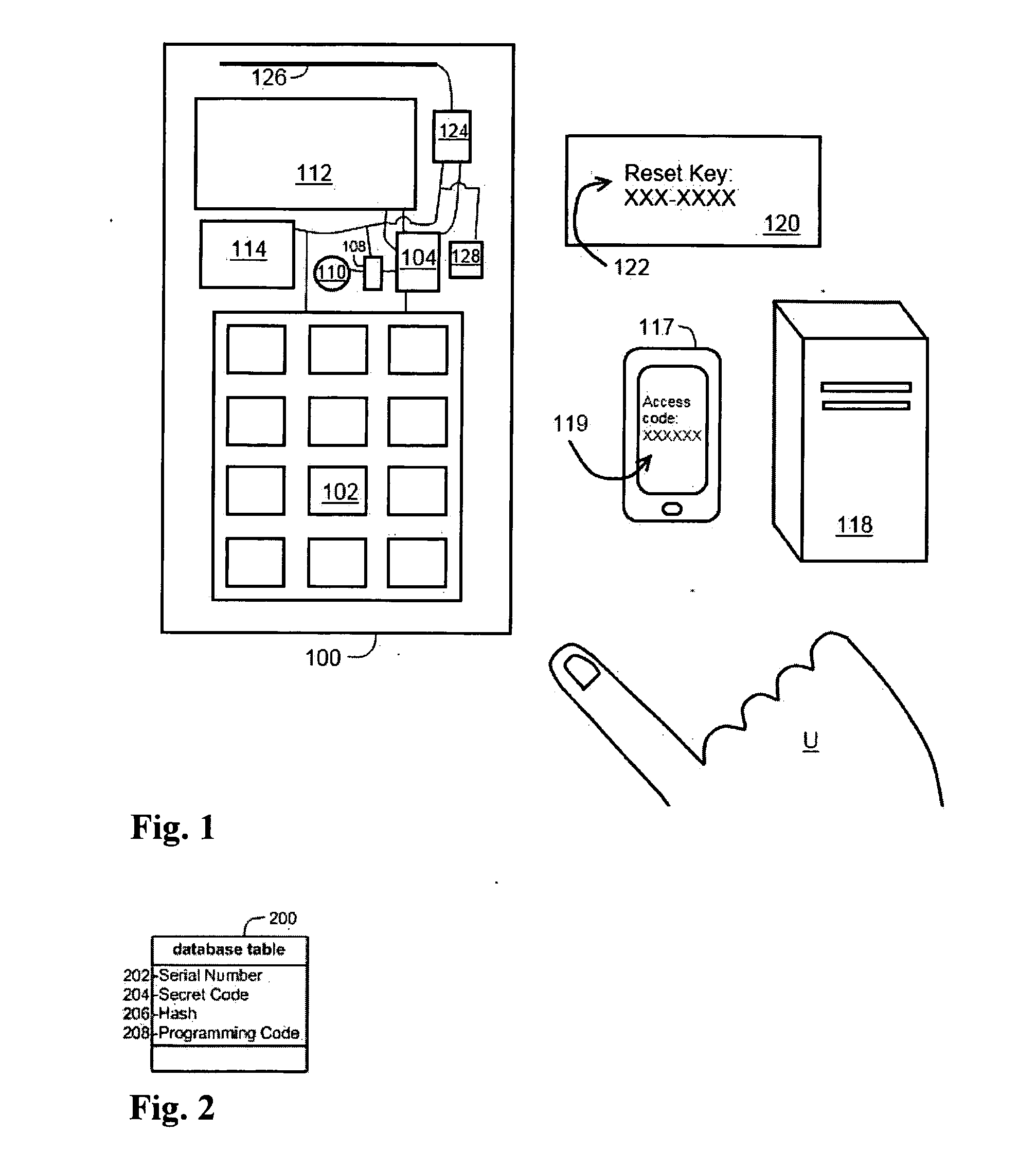
[0036]With reference to the accompanying Figures, in accordance with the present invention, a lock, system and method for providing low-maintenance, dynamic access to an un-networked lock are described in this section. That is, the lock is automatically reprogrammed periodically without communicating with a remote server. In this way, the lock, for example, allows a property manager to give a guest a code that will allow the guest to enter a rental property for only the period of the guest's stay. Currently, a manager must either manually change the code after the guest's stay is complete, the lock must connect to a network, or the lock must be reprogrammed by a key device that instructs the lock to change its access “code” from an old code to a new code. It is to be understood for the purposes of this description that “code,” unless otherwise specified, can refer either to an electronic signal or pattern associated with a key device or to a sequence of alphanumeric or other symbols...


PUM


Abstract

An electronic lock, system and method for dynamic controlled access, without the lock communicating with or connected to a code server, are provided. The lock includes a locking mechanism, a clock, a microprocessor, and a memory storing a hash function and programmed instructions for the microprocessor to perform certain operations. The microprocessor and memory may be comprised in a microcontroller. When an access code is entered into the lock, the lock microcontroller hashes currently valid access start date / duration combinations with lock identifying data to return valid access codes. If the entered access code equals any of the valid access codes, the locking mechanism is opened. The lock identifying data may include data stored by a lock manufacturer and / or data created by a lock owner. Static access codes may also be programmed into the lock if desired. Caching of valid access codes may be used to reduce processing time.

Description

FIELD OF THE INVENTION[0001]The present invention relates to electronic locks, systems and methods for providing dynamic access without a lock communicating with a remote server. More particularly, it relates to coded-entry locks having a plurality of valid access codes at any given time corresponding to a plurality of overlapping time periods of validity that include the given time.BACKGROUND OF THE INVENTION[0002]Electronic locks are widely used in situations in which it is desired to provide a guest or customer (termed generically “guest” herein) with secure access to something (e.g., a hotel room, a locked bicycle or motor vehicle, or a safe or storage locker) for an agreed upon period of time, as they can typically be programmed to accept a certain code, radio frequency, magnetic card or other entry means for the time period and then reprogrammed at the end of the time period to no longer accept the entry means. Electronic locks may be grouped into two basic categories, namely,...

Claims


Application Information

Patent Timeline
Patent Type & Authority Applications(United States)
IPC IPC(8): G05B19/00
CPCG07C9/00571G07C2209/08G07C9/00817G07C9/0069Y10T70/70
Inventor GREISEN, DAVID J.GREISEN, DANIEL H.
Owner GREISEN ENTERPRISES
Why Eureka
Try Eureka