System and method for diffuse imaging with time-varying illumination intensity

a technology of illumination intensity and diffuse imaging, applied in the field of forming images with light, can solve the problems of limited prior art, methods that do not use time-resolved light measurement by light meters, and the inability to infer the time-varying intensity of incident light intensity

Active Publication Date: 2013-02-21
MASSACHUSETTS INST OF TECH
View PDF5 Cites 11 Cited by
  • Summary
  • Abstract
  • Description
  • Claims
  • Application Information

AI Technical Summary

Benefits of technology

[0009]The present invention overcomes the aforementioned drawbacks of previous imaging systems and methods by generating a digital image with spatial resolution finer than the smaller of the spatial support of the illumination intensity characteristic and the spatial support of the light meter sensitivity characteristic using light directed at a scene to be imaged that has time-varying intensity. In a preferred embodiment of the invention, a plurality of time-resolved light meters is provided for receiving light reflected from the scene to generate time-resolved samples of the intensity of light incident at each light meter; systems and methods involving only one light meter are also described. The temporal variation in the intensity of light incident at each sensor is related to radiometric properties of the scene, and a computer means processes site discrete-time samples to form a digital image. For any fixed desired image accuracy, suitable illumination bandwidth, sampling frequency, number of illumination spatial intensity characteristics, number

Problems solved by technology

This means that while each light meter may have a sensitivity to incident light that varies with time—for example, using a shutter or any other method known to those skilled in the art—the light meter produces a single measurement, so variation of the incident light intensity with time cannot be inferred.
These methods do not use time-resolved measuremen

Method used


Image

  • System and method for diffuse imaging with time-varying illumination intensity
  • System and method for diffuse imaging with time-varying illumination intensity
  • System and method for diffuse imaging with time-varying illumination intensity

Examples


Embodiment Construction

[0020]The invention is described through one exemplary configuration. Those skilled in the art can generate many other configurations.

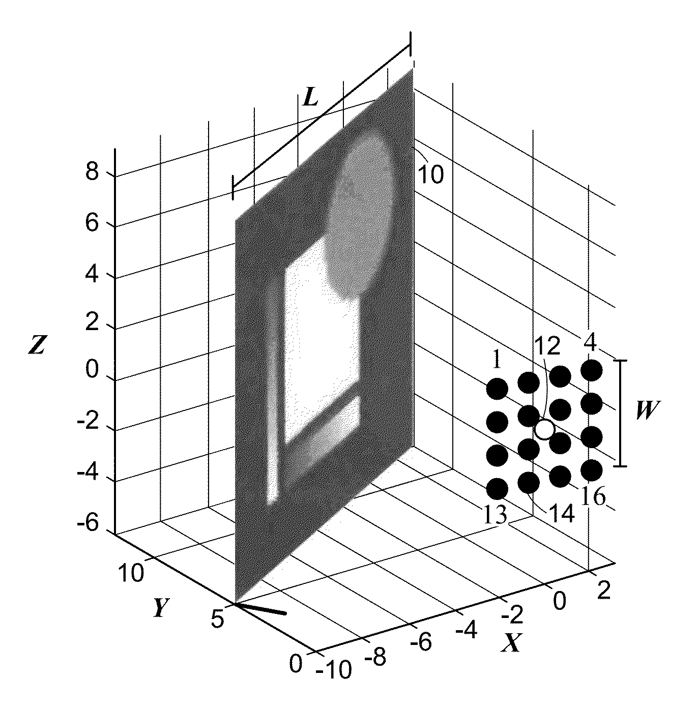
[0021]Consider the imaging scenario depicted in FIG. 1, with a planar surface 10 to be imaged, a single, time-varying, monochromatic, omnidirectional illumination source 12, and omnidirectional time-resolved light meters 14 indexed by kε[1, 2, . . . , K]. Those skilled in the art can modify the method described herein to include spatial variation of the illumination intensity, termed an illumination spatial intensity characteristic, and / or spatial variation of the sensing efficiency. Those skilled in the art can generate variations in spatial intensity characteristics and / or sensing efficiency through the use of spatial light modulators including, but not limited to, those based on liquid crystals and digital micromirror devices.

[0022]We assume that the position, orientation, and dimensions (L-by-L) of the planar surface 10 are known. Many methods for...


PUM


Abstract

Diffuse image measurement system and digital image formation method. The system includes a source of light with time-varying intensity directed at a scene to be imaged. A time-resolved light meter is provided for receiving light reflected from the scene to generate time-resolved samples of the intensity of light incident at the light meter. The temporal variation in the intensity of light incident at the light meter is associated with a function of a radiometric property of the scene, such as a linear functional of reflectance, and a computer processes the samples to construct a digital image. The spatial resolution of the digital image is finer than the spatial support of the illumination on the scene and finer than the spatial support of the sensitivity of the light meter. Using appropriate light sources instead of impulsive illumination significantly improves signal-to-noise ratio and reconstruction quality.

Description

[0001]This application claims priority to provisional application No. 61 / 524795 filed on Aug. 18, 2011, the contents of which are incorporated herein by reference.[0002]This invention was made with government support under Grant No. CCF-0643836 awarded by the National Science Foundation. The government has certain rights in this invention.BACKGROUND OF THE INVENTION[0003]This invention relates to forming images with light, where the image is determined computationally from time-resolved measurements. The spatial resolution of the computed image is finer than the spatial support of the illuminations and finer than the spatial support of the sensitivities of the light meters. In an embodiment representing a limiting case, images are formed with a single illumination extending across the entire scene and each light meter sensitive to the entire scene.[0004]Imaging is distinguished from other forms of sensing by having the goal of producing an image—a representation in one-to-one spatia...

Claims


Application Information

Patent Timeline
IPC IPC(8): H04N7/18
CPCG01J1/0437G01J1/08G06T2207/20221G06T5/50G06T2207/10152G01J1/4228G03B39/005G03B39/00
Inventor KIRMANI, GHULAM AHMEDGOYAL, VIVEK K.
Owner MASSACHUSETTS INST OF TECH
Why Eureka
Try Eureka