Cross flow wind or hydrokinetic turbines

a technology of hydrokinetic turbines and wind turbines, which is applied in the direction of propulsive elements, motors, propulsive components, etc., can solve the problems of low efficiency, excessive vibration, and lack of starting torque, and achieve the effect of increasing the effective swept area

Inactive Publication Date: 2013-02-21
KIRKE BRIAN KINLOCH
View PDF6 Cites 15 Cited by
  • Summary
  • Abstract
  • Description
  • Claims
  • Application Information

AI Technical Summary

Benefits of technology

[0021]The axis of rotation of the turbine in water may be inclined in use at an angle of app

Problems solved by technology

They lack starting torque, have low efficiency and where hydrokinetic turbines have their blades at a fixed pitch, excessive vibration occurs.
Generally the mechanisms which have been proposed or used for this purpose are relativel

Method used


Image

  • Cross flow wind or hydrokinetic turbines
  • Cross flow wind or hydrokinetic turbines
  • Cross flow wind or hydrokinetic turbines

Examples


Embodiment Construction

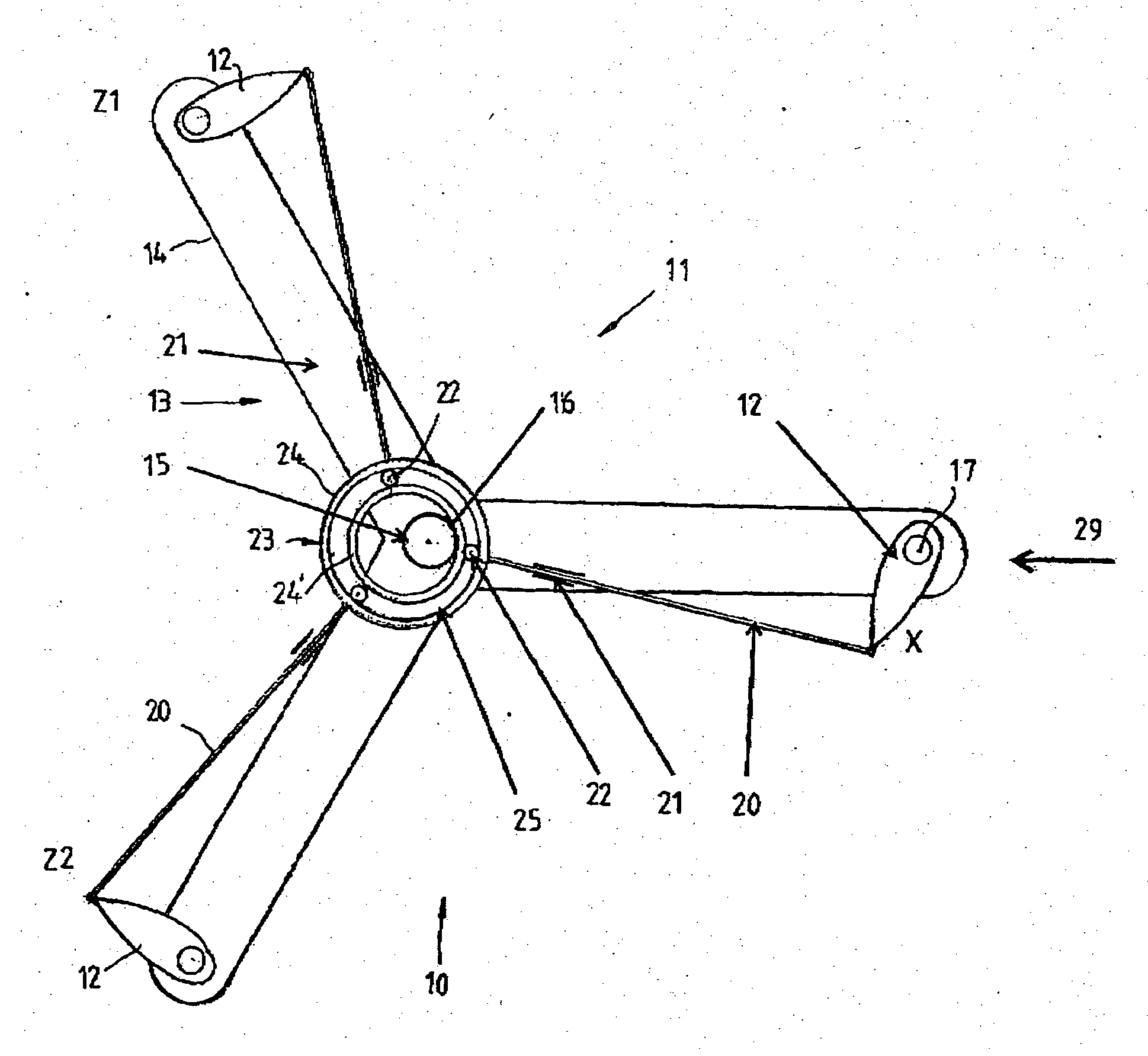
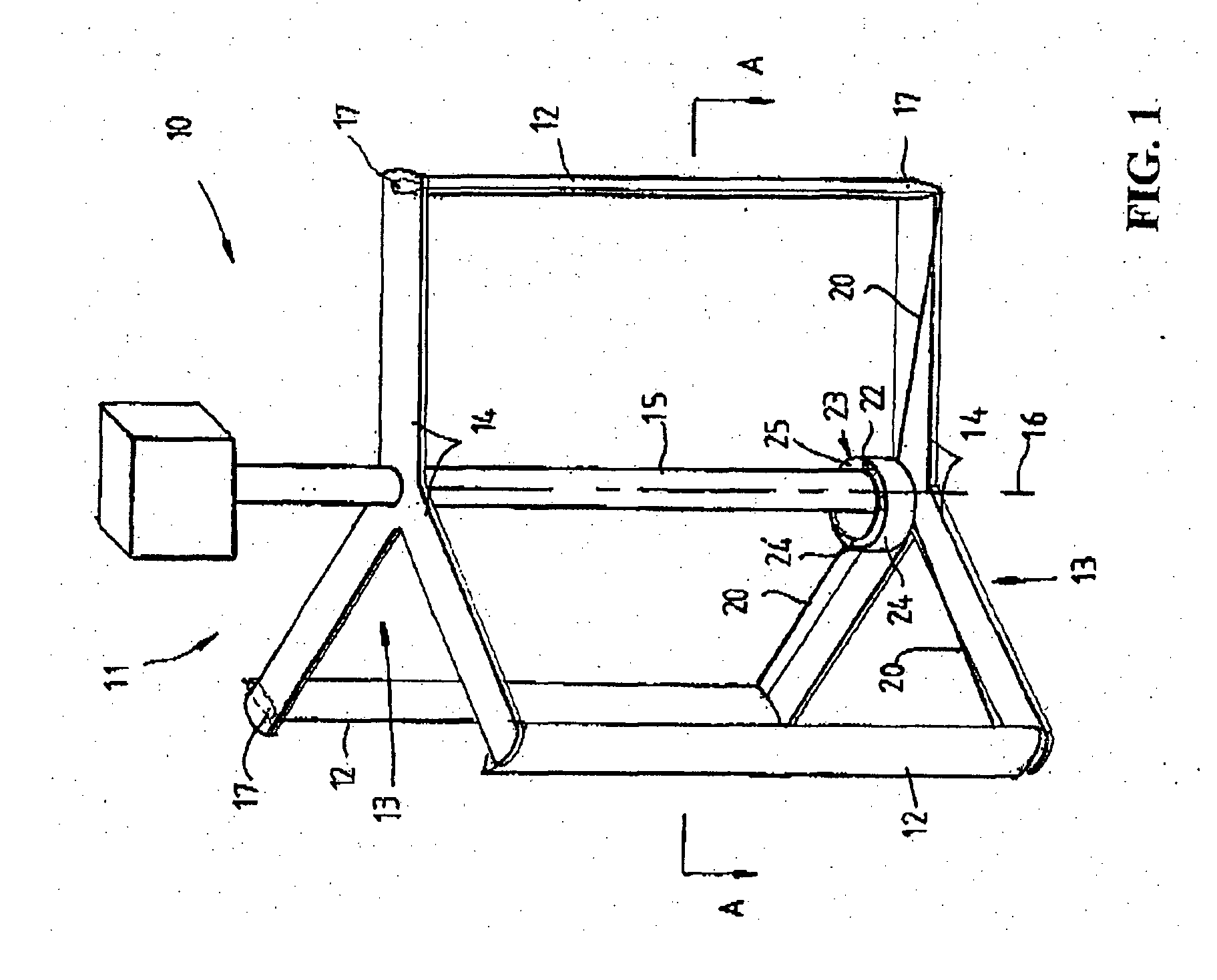
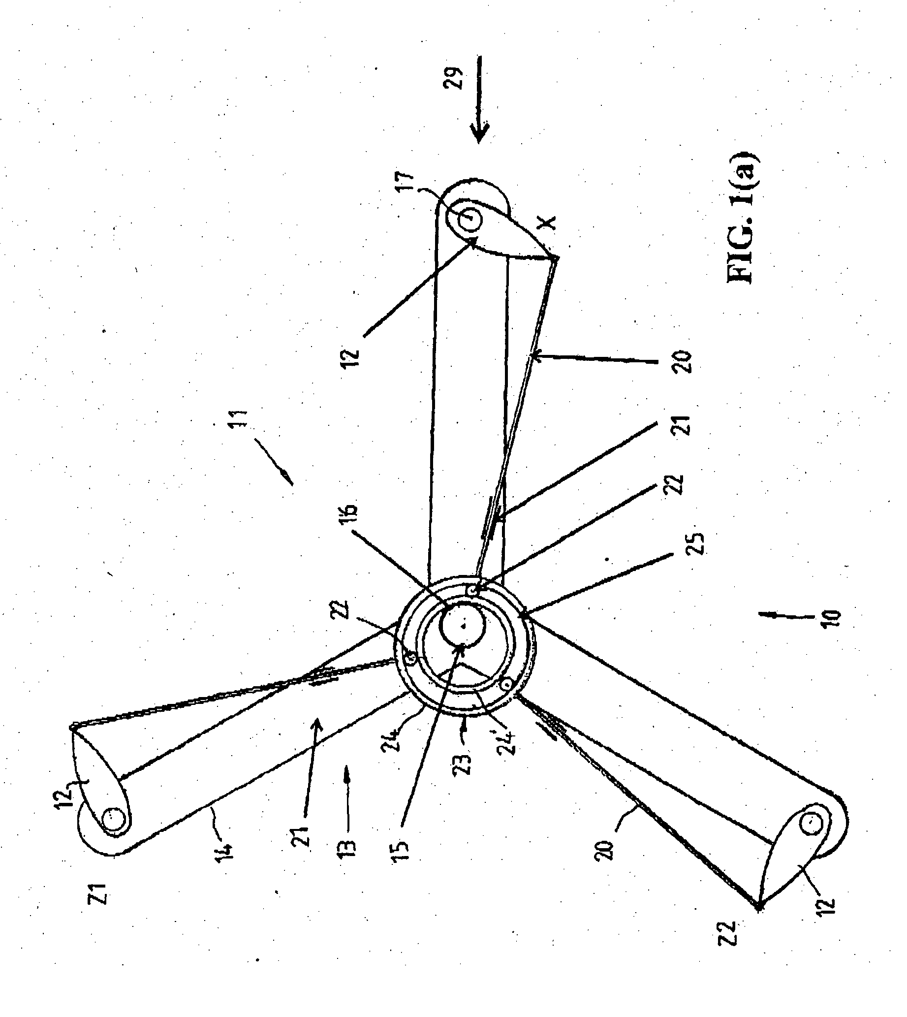
[0039]Referring to the drawings and firstly to FIGS. 1, 1(a) and (b), there is illustrated a turbine 10 according to one preferred embodiment of the invention comprising a turbine rotor 11 having a plurality of straight or linear blades 12, in this case three blades, which are mounted on a common radius and at equi-spaced circumferential positions to a support frame comprising first and second sets 13 of radial arms 14, each set 13 of arms 14 being fixedly mounted at spaced apart axial positions to a central shaft 15. The blades 11 are mounted to the arms 14 so that they are maintained parallel to the axis of rotation 16 of the turbine rotor 11 defined by the shaft 15.

[0040]Each blade 12 is pivotally attached adjacent its leading edge at opposite end pivot points 17 to two axially spaced apart parallel radial arms 14 such that each blade 12 is pivotally mounted to and extends between pairs of spaced aims 14. A rigid link 20 is pivotally attached to each blade 12 adjacent its trailin...


PUM


Abstract

A turbine (10) comprising a turbine rotor (11) having a blade support frame (13), and a plurality of blades (12) each pivotally mounted adjacent to its leading edge to the frame (13) for rotation about an axis extending substantially parallel to the axis of rotation of the rotor (11) with the trailing edge of each blade (12) being capable of pivoting downstream or downwind due to fluid dynamic forces on each blade. Pitch control means in the form of a ring or guide (23) is located around the shaft (15) and is coupled via links or lines (20) to the trailing end of each blade (12) to control the pitch of each blade (12) during rotation of the turbine rotor (11).

Description

TECHNICAL FIELD[0001]This invention relates to cross flow wind or hydrokinetic turbines and in particular to turbines which includes passive means to control the pitch of the blades of the turbines.BACKGROUND ART[0002]Cross flow Darrieus type wind and water turbines have a number of inherent disadvantages. They lack starting torque, have low efficiency and where hydrokinetic turbines have their blades at a fixed pitch, excessive vibration occurs. To overcome these disadvantages, turbines have been proposed which have different mechanisms for adjusting the pitch of the blades of the turbines. Generally the mechanisms which have been proposed or used for this purpose are relatively complex.[0003]A further disadvantage of turbines of the above type is that they use large shafts which are relatively expensive and step-up gearboxes or multipole generators due to the low rotational speed achieved with such turbines.[0004]Patent application Nos. WO2001062018, WO2009082352 and KR2004002831 ...

Claims


Application Information

Patent Timeline
IPC IPC(8): F03D3/06F03D7/06F03D11/00
CPCF03D3/068Y02E10/74F05B2210/16F03D7/06
Inventor KIRKE, BRIAN KINLOCH
Owner KIRKE BRIAN KINLOCH
Why Eureka
Try Eureka