Refrigeration compressor

a refrigeration compressor and compressor technology, applied in the direction of pump components, positive displacement liquid engines, liquid fuel engine components, etc., can solve the problems of the performance of refrigeration compressors, achieve the effects of improving the performance of the compressor, reducing the internal temperature reliably and efficiently, and increasing the thermal efficiency of the compressor

Inactive Publication Date: 2013-02-21
WHIRPOOL SA
View PDF2 Cites 6 Cited by
  • Summary
  • Abstract
  • Description
  • Claims
  • Application Information

AI Technical Summary

Benefits of technology

[0013]Accordingly, the present invention takes advantage of the thermodynamics existing between the compressor and the compression system, achieving the reduction of internal temperatures reliably and efficiently and hence improving the performance of the compressor.SUMMARY OF THE INVENTION
[0014]The present invention achieves the above objects by means of a hermetic compressor comprising a housing which encloses the component parts of the compressor, with a heat accumulating material—or a change-phase material—occupying an internal volume or adjacent to the compressor housing. The change-phase material acts as a thermal capacitor able to absorb high amounts of heat while the compressor is on and to reject heat while the compressor is off, in order to increase the thermal efficiency of the compressor.

Problems solved by technology

One major issue of the refrigeration industry is the performance of refrigeration compressors.

Method used


Image

  • Refrigeration compressor
  • Refrigeration compressor
  • Refrigeration compressor

Examples


first embodiment

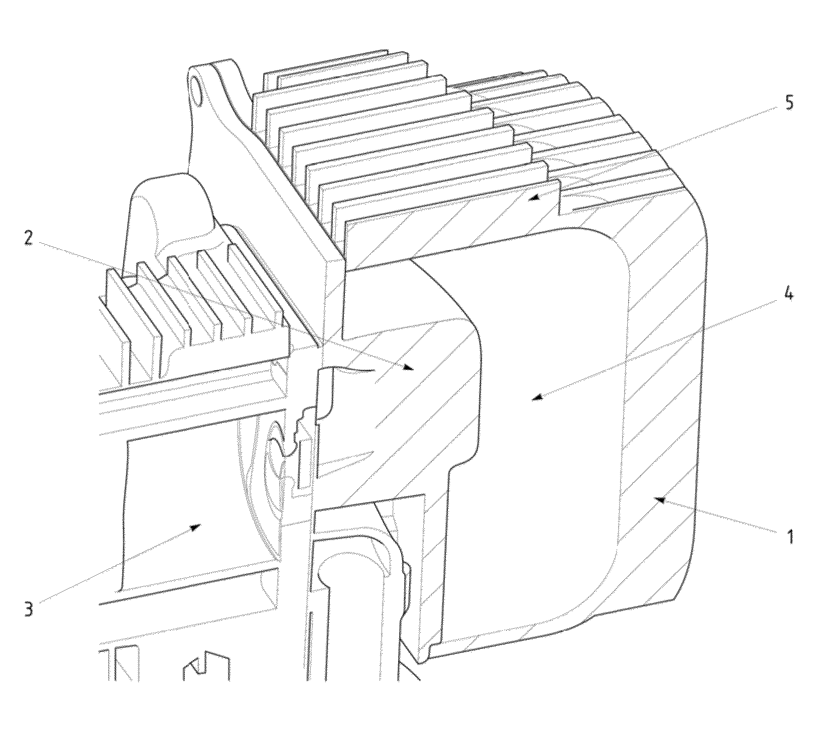
[0051]FIG. 1 shows the present invention, where the heat accumulating material is located in a volume formed between a casing which surrounds the cylinder cap and the compressor cylinder cap.

[0052]This region of the cylinder cap is critical for the compressor, since various gas communications flow therethrough. The suction gas, in order to get into the cylinder, passes over the region of the suction muffler which is in contact with the cylinder cap. The high temperature gas from the compression is also discharged to the cap, from where it follows to the remainder of the discharge system. Thus, by removing the gas heat on the cylinder cap and hence lowering the temperature thereof, one may observe a lower heating on the suction muffler output and the heat dissipation throughout the discharge system downstream the cap is reduced, since the temperature potential between the gas itself and the internal environment of the compressor is decreased. In addition, the cap, upon cooling, absor...

third embodiment

[0066]FIGS. 5a, 5b, and 5c show the present invention, wherein the heat accumulating material is employed externally to the region of the compressor crankcase 8.

[0067]As shown in FIG. 5a, in this embodiment a volume of phase-change material 6 is provided on the lower portion of the compressor in a volume separate from the internal environment of the compressor. This volume may assume the form of a reservoir 9 to be closed by means of welding, gluing, or other forms that can assure the airtightness of the subject region, so as to ensure the sealing between the internal compressor volume and the heat accumulator volume.

[0068]As shown in FIGS. 5a to 5b, this reservoir 9 may include metal fins 10 in the region of the heat accumulator volume, in order to facilitate the heat transfer from the heat accumulating material into the external environment, thereby maximizing the efficiency of the heat discharge process.

[0069]The embodiment shown in FIGS. 5a-5c has two significant advantages: Onc...

sixth embodiment

[0090]Thus, in the present invention, the heat accumulating material acts on the cooling of the gas when it passes through the tube 19, reducing its temperature on the cylinder entrance, and consequently increasing the energetic and volumetric efficiency.

[0091]Where a latent heat accumulator (PCM) is used, the phase change temperature should be lower than the gas temperature at the region of the tube, such as to generate a temperature potential which favors heat removal. One may choose a sensitive heat accumulator (e.g., water or oil), however, this design should be carefully planned in order to ensure the thermal discharge of the heat accumulator while the compressor is off.

[0092]Similarly to what was said with respect to the other embodiments of the present invention, the fins as seen in the drawings are only an illustrative embodiment, and whether they should be provided depends upon the application design for the heat accumulator. The provision of such fins aims at enhancing gas...


PUM


Abstract

The present invention relates to a thermally efficient refrigeration compressor, comprising a housing which surrounds the component parts of the compressor and a heat accumulating material occupying a volume internal (4, 7, 15, 18, 23, 27) or adjacent (9, 11, 30, 32, 37) to the compressor housing. Accordingly, the present invention takes advantage of the thermodynamics existing between the compressor and the refrigeration system, achieving a reduction of the internal temperatures reliably and efficiently and consequently improving the performance of the compressor.

Description

FIELD OF THE INVENTION[0001]The present invention relates to a refrigeration compressor and, more particularly, to a compressor whose cooling is carried out by using characteristics from its thermal transient when said compressor is applied to a refrigeration system.BACKGROUND OF THE INVENTION[0002]A compressor has the function of increasing the pressure of a certain fluid volume to a pressure required for carrying out a refrigeration cycle. In the refrigeration industry, it is common to use hermetic compressors generally comprising a sealed housing where the compressor parts are mounted: a motor-compressor assembly comprising a cylinder block having an end closed by a cylinder head which defines a discharge chamber in communication with a compression chamber defined inside the cylinder, the compression chamber being closed by a valve plate provided between the cylinder end and the cylinder head.[0003]During the operation of the compressor, the heat generated by compression of gases...

Claims


Application Information

Patent Timeline
Patent Type & Authority Applications(United States)
IPC IPC(8): F04B53/00
CPCF04B39/06F05C2251/048F04B53/08F04B39/121F04B39/12
Inventor JUNIOR, FERNANDO ANTONIO RIBASKREMER, RODRIGO
Owner WHIRPOOL SA
Why Eureka
Try Eureka