
Cable connector, receptacle connector and connector assembly thereof with improved contact arrangement

Inactive Publication Date: 2013-02-21
KUNSHAN LIANTAO ELECTRONICS CO LTD
View PDF36 Cites 24 Cited by
  • Summary
  • Abstract
  • Description
  • Claims
  • Application Information

AI Technical Summary

Benefits of technology

The patent text describes a cable connector and receptacle connector that can be easily joined together. When joined, the cable connector's tongue plate is placed in the receptacle connector's receiving slot, and the contacts on each connector make contact with pads on the PCB tongue plate to allow for signal transmission. This design helps to control the impedance of the entire transmission system, reducing signal attenuation and reflection. Overall, this improves the quality of the signals transmitted through the cables.

Problems solved by technology

However, it is difficult for impedance matching among the board connector, the mother board and the cables according to the conventional connector ports, as a result that the high-frequency performance of the conventional connector ports is poor and signal distortion may so much as occur in transmission.

Method used


Image

  • Cable connector, receptacle connector and connector assembly thereof with improved contact arrangement
  • Cable connector, receptacle connector and connector assembly thereof with improved contact arrangement
  • Cable connector, receptacle connector and connector assembly thereof with improved contact arrangement

Examples


Embodiment Construction

[0045]Reference will now be made to the drawing figures to describe some preferred embodiments in detail. FIGS. 20 to 22 illustrate a connector assembly 300 including a receptacle connector 200 for mounting to a circuit board 400 and a cable connector 100 for mating with the receptacle connector 200. According to the illustrated embodiments, both the cable connector 100 and the receptacle connector 200 are compatible to USB 3.0 protocol.

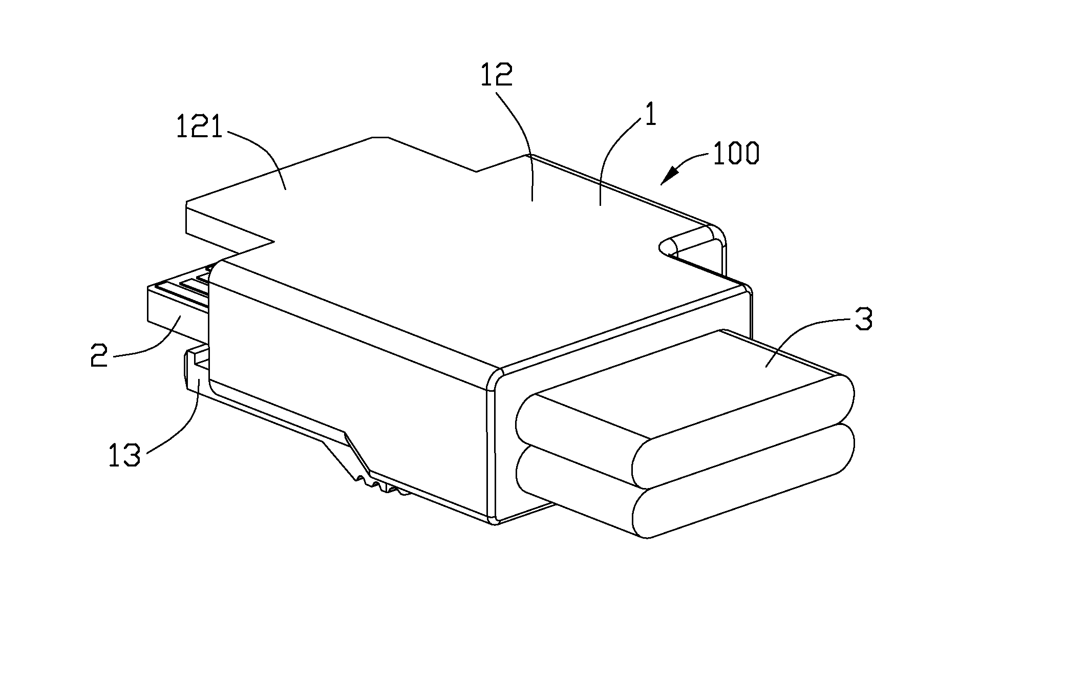
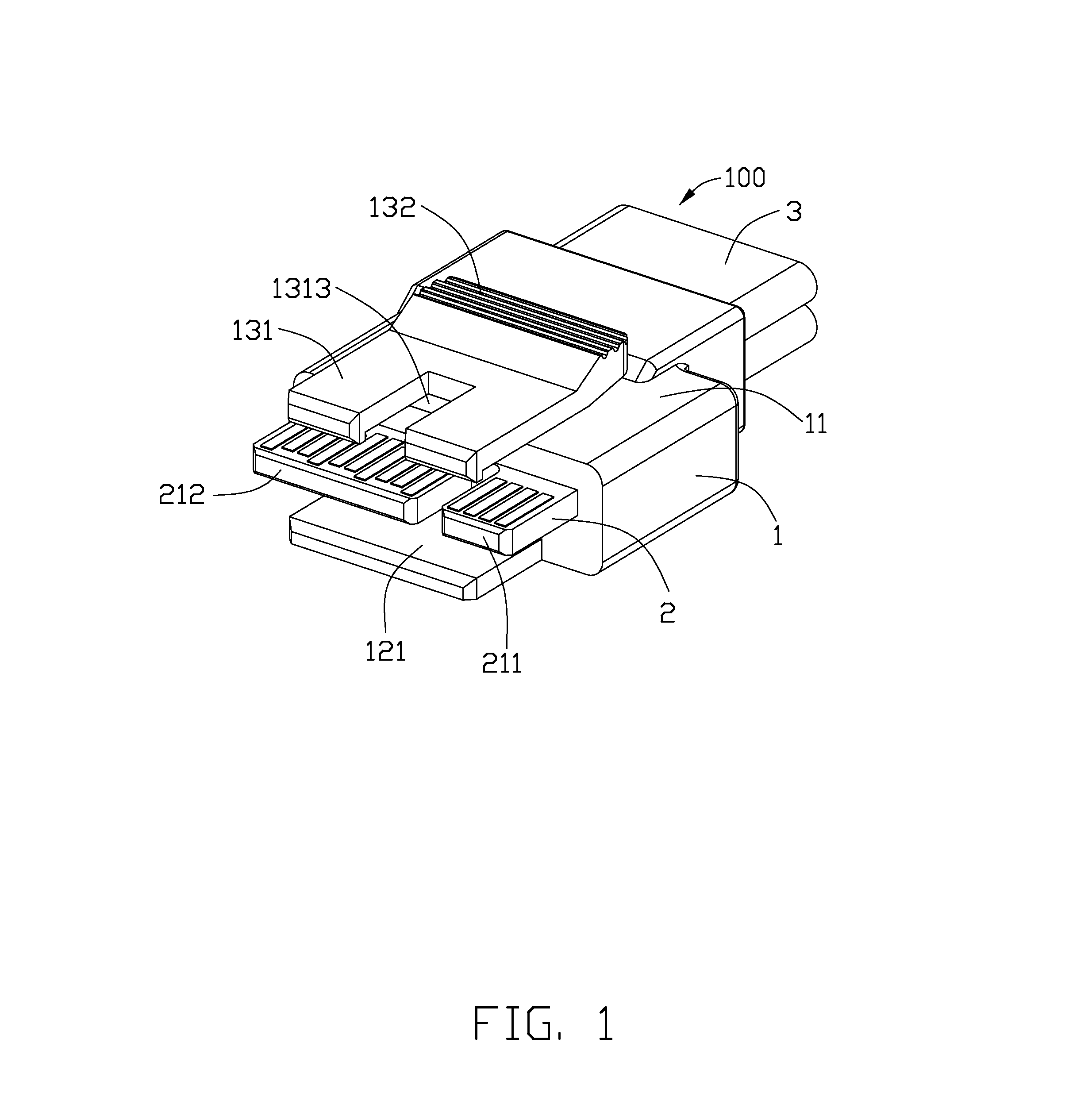
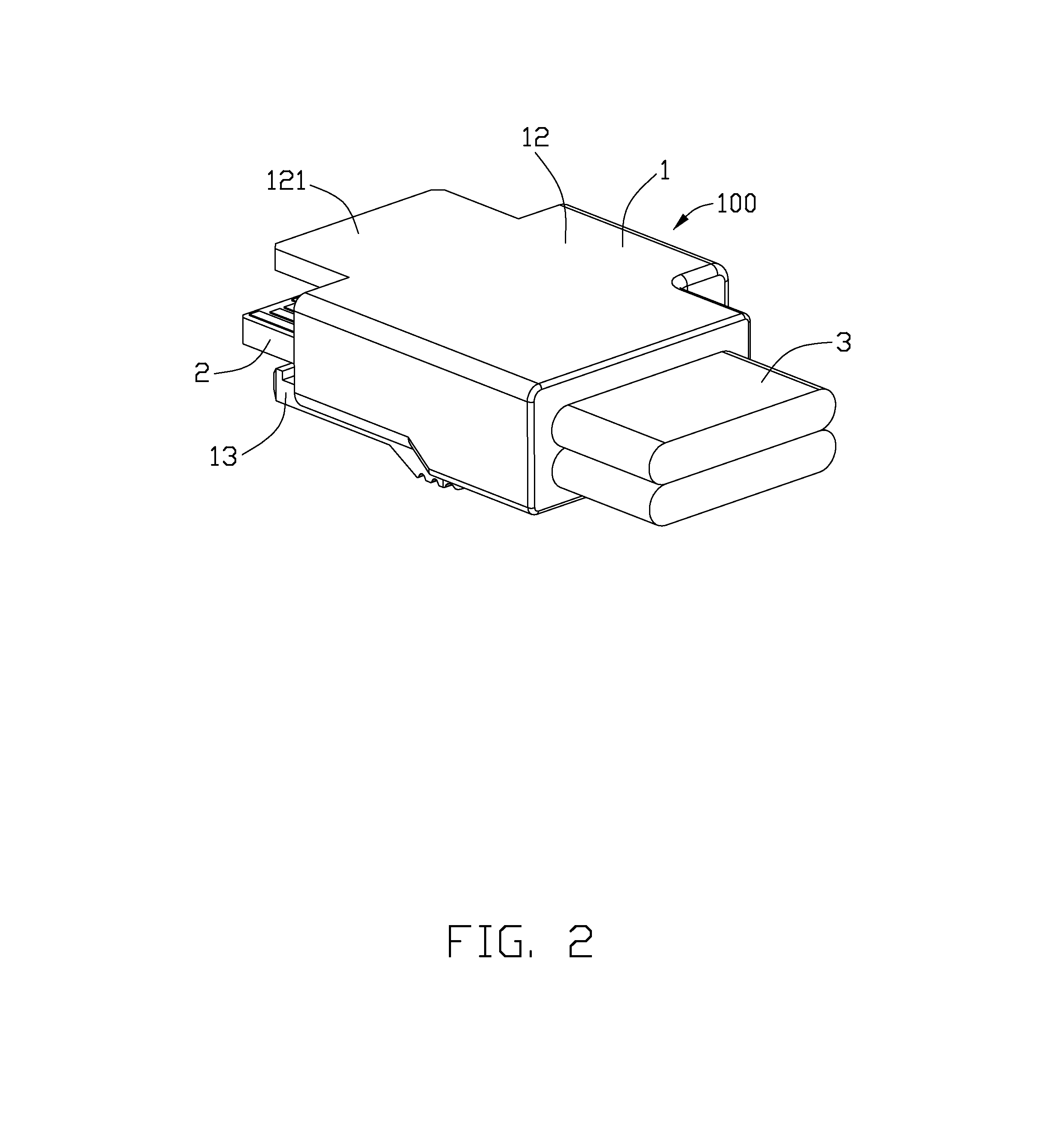
[0046]Referring to FIGS. 1 and 2, the cable connector 100 includes an insulative plug housing 1, a paddle printed circuit board (PCB) 2 retained in the plug housing 1 and a pair of cable assemblies 3 each including a plurality of cables (not labeled) for electrically connecting with the paddle PCB 2.

[0047]Referring to FIGS. 3 to 6, the plug housing 1 includes a mating surface 101 and a mounting surface 102 opposite to the mating surface 101. From a structure view, the plug housing 1 includes a first exterior wall 11, a second exterior wall 12 opposit...


PUM


Abstract

A connector assembly includes a cable connector and a receptacle connector. The receptacle connector includes a receptacle housing defining a receiving slot and a number of contacts including multiple first contacts and multiple second contacts. The second contacts include a number of differential signal contacts and ground contacts among which the differential signal contacts are paired and the ground contacts are located at opposite lateral sides of each paired differential signal contacts. The first contacts are ordinally arranged as GGVV, or VGVG, or VVGG, or GVGV, or GVVG, or VGGV, or VSSG, or GSSV. The second contacts are compatible to USB 3.0 protocol for high-speed signal transmission. As a result, it is easy to control the impedance of the whole transmission system so as to decrease signal attenuation and signal reflection.

Description

BACKGROUND[0001]1. Technical Field[0002]The present disclosure relates to a cable connector, a receptacle connector and a connector assembly thereof, and more particularly to a high-speed cable connector, a high-speed receptacle connector and a connector assembly thereof with improved paddle PCB as a tongue plate for impedance matching and cross-talk reduction.[0003]2. Description of the Related Art[0004]Universal Serial Bus (USB) has been widely used in electronic products due to its stable transmission speed and high performance. With the development of the USB port protocol, it will surely transit to USB 3.0 version after USB 1.0 version and USB 2.0 version. Comparing with the USB 2.0 port, the USB 3.0 port is provided with transmission speed ten times faster. Presently, it is a flat connector port developed by Intel which can support the USB 3.0 protocol. The flat connector port includes a board connector for mounting on a mother board and a cable connector for mating with the b...

Claims


Application Information

Patent Timeline
IPC IPC(8): H01R24/28
CPCH01R12/62H01R13/6471H01R12/714
Inventor GUI, YONG-NANWU, LINCHENG, WEI-YA
Owner KUNSHAN LIANTAO ELECTRONICS CO LTD
Learn More