Sandblasting apparatus

Inactive Publication Date: 2013-02-21
HONG FU JIN PRECISION IND (SHENZHEN) CO LTD +1
View PDF13 Cites 0 Cited by
  • Summary
  • Abstract
  • Description
  • Claims
  • Application Information

AI Technical Summary

Benefits of technology

The patent describes how vacuum coating apparatus can become coated with films during the process. These films can affect the performance of the apparatus. The apparatus can be cleaned off using a sandblasting apparatus, but it must be frequently adjusted to maintain a certain angle and is therefore not very efficient. The invention aims to improve the efficiency of the sandblasting apparatus.

Problems solved by technology

As such, the efficiency of use of the sandblasting apparatus is low.

Method used


Image

  • Sandblasting apparatus
  • Sandblasting apparatus
  • Sandblasting apparatus

Examples


Embodiment Construction

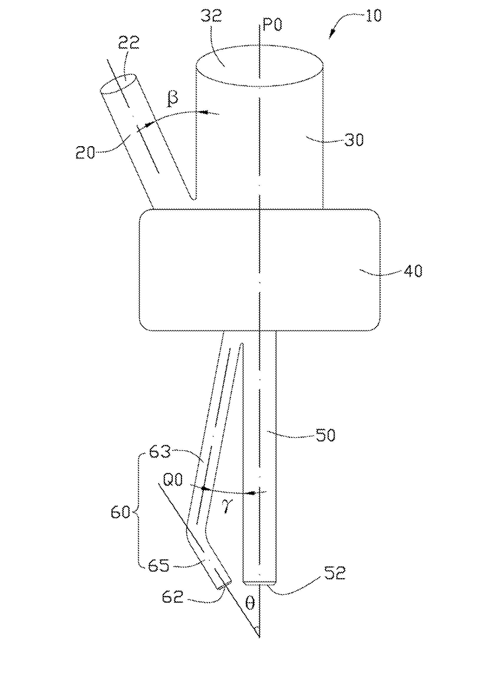
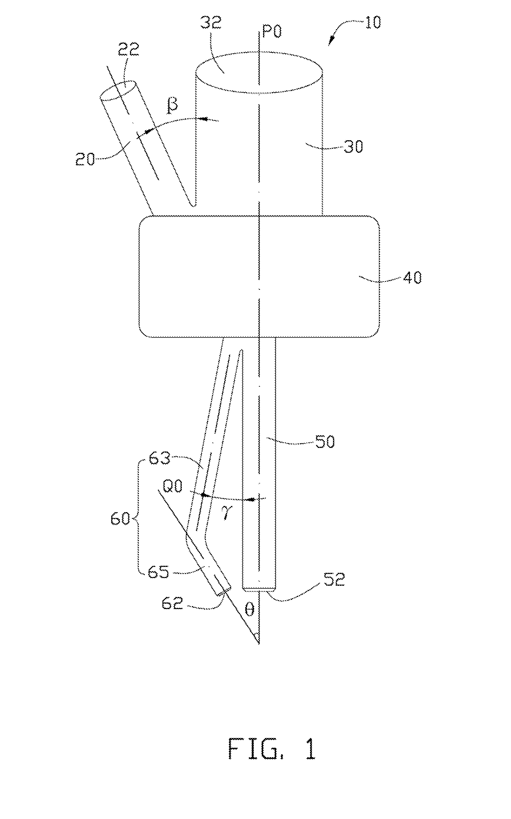
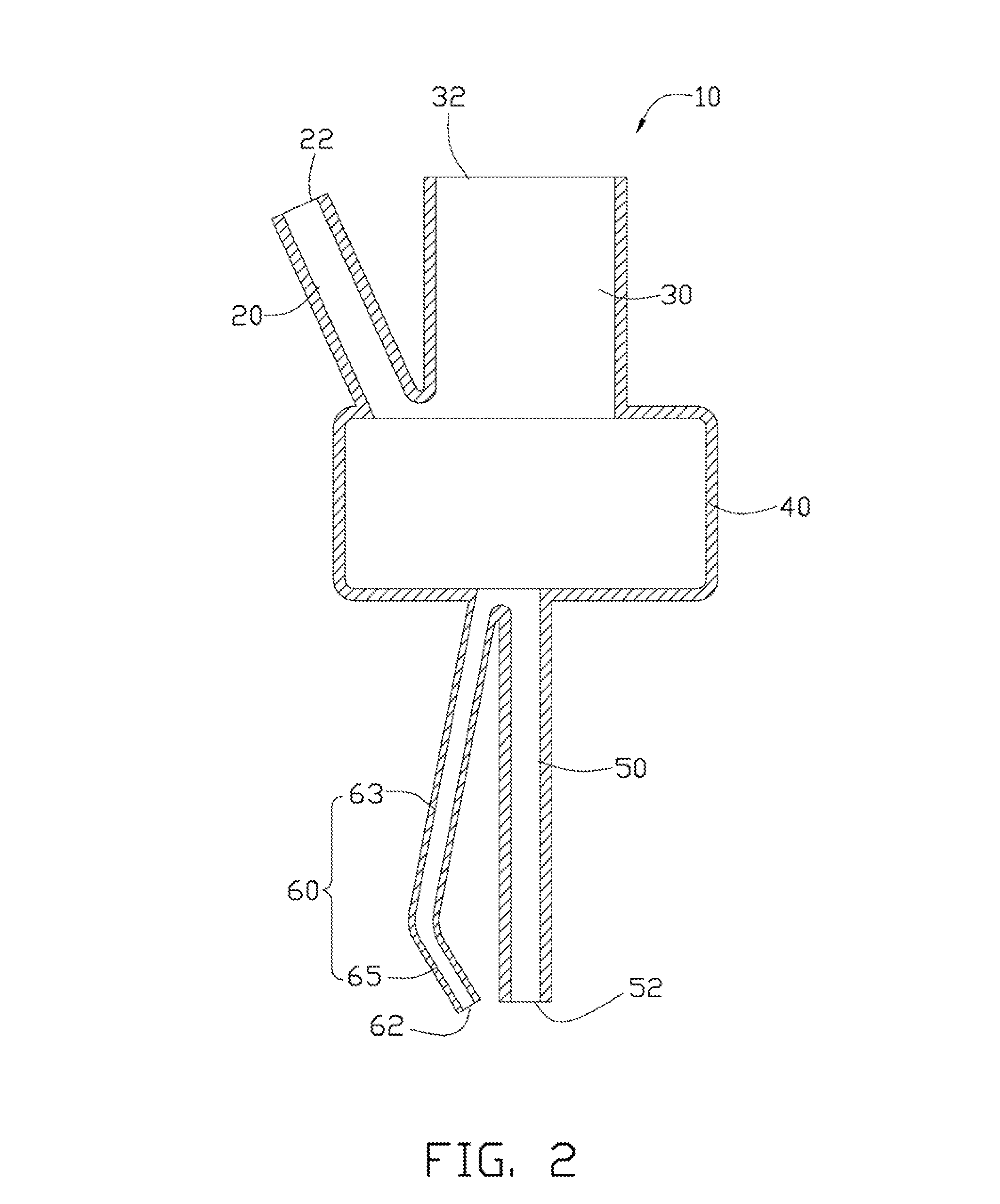
[0011]FIGS. 1 and 2 show a sandblasting apparatus 10 according to an exemplary embodiment. The sandblasting apparatus 10 may be used for removing coatings from coated articles by spraying sand particles. The sandblasting apparatus 10 includes a sand tube 20, a fluid tube 30, a mixing chamber 40, a major output tube 50 and an auxiliary output tube 60. In this embodiment, the fluid tube 30 is integrally formed with the sand tube 20. The major output tube 50 is integrally formed with the auxiliary output tube 60.

[0012]The sand tube 20 is substantially tubular and straight. The sand tube 20 defines a sand inlet 22 at one end. The sand inlet 22 may be used for inputting sand particles. Another end of the sand tube 20 connects and communicates with the mixing chamber 40.

[0013]The fluid tube 30 is substantially tubular and straight. The fluid tube 30 defines a fluid inlet 32 at one end thereof. A gaseous or liquid fluid substance, such as air or water may be input into the fluid inlet 32. ...


PUM


Abstract

A sandblasting apparatus comprises a sand tube for the input of sand particles, a fluid tube for the input of a fluid substance, the fluid tube and the sand tube cooperatively defining an acute angle; a mixing chamber communicating with the sand tube and the fluid tube, a major output tube communicating with the mixing chamber; and an auxiliary output tube including a first part and a second part. The first part communicates with the mixing chamber and the second part. The second part extends towards the major output tube, offset from the axial direction of the first part. The axis of the second part and the axis of the major output tube cooperatively define an acute angle.

Description

BACKGROUND[0001]1. Technical Field[0002]The present disclosure generally relates to a sandblasting apparatus.[0003]2. Description of Related Art[0004]Internal parts of vacuum coating apparatus, such as a rotating bracket, become coated with films during process of vacuum coating. The increasing thickness of the films can influence the performance of the vacuum coating apparatus. The films may be cleaned off by a sandblasting apparatus. The sandblasted particles can be mixed with hyperbaric air or hyperbaric water to strike the films with a high speed. However, to obtain a high cleaning efficiency, the sandblasting apparatus must be frequently adjusted to maintain a 45 degrees spraying angle relative to the film. As such, the efficiency of use of the sandblasting apparatus is low.[0005]Therefore, there is room for improvement within the art.BRIEF DESCRIPTION OF THE FIGURES[0006]Many aspects of the disclosure can be better understood with reference to the figures. The components in th...

Claims


Application Information

Patent Timeline
IPC IPC(8): B24C7/00
CPCB24C3/02B24C7/0046B24C5/02B24C3/04
Inventor CHANG, HSIN-PEIHUANG, TENG-TSUNGPENG, LI-QUAN
Owner HONG FU JIN PRECISION IND (SHENZHEN) CO LTD
Why Eureka
Try Eureka