Anti-reflective film and optical element having anti-reflective film

a technology of anti-reflective film and optical element, which is applied in the field of anti-reflective film, can solve the problems of not being able to make reflectance low for a light, having 6 layers of anti-reflective film, and having no effect on light reflection, etc., and achieves good characteristics, good characteristics, good effects

Inactive Publication Date: 2005-12-22
CANON KK
View PDF8 Cites 24 Cited by
  • Summary
  • Abstract
  • Description
  • Claims
  • Application Information

AI Technical Summary

Benefits of technology

[0009] It is, therefore, an object of the present invention to provide an anti-reflective film of a 6-layer or 8-layer structure using fluoride thin films that is effective for a light of a wavelength of about 140 to 210 nm.
[0010] It is another object of the present invention to realize an anti-reflective film that has a low reflectance for a light incident at such a large angle as 30 degrees or more, without increasing the whole thickness of the film.

Problems solved by technology

In addition, an anti-reflective film having six layers disclosed in U.S. Pat. No. 6,472,087 above has a problem that the reflectance cannot be made low for a light. incident at such a large angle as 30 degrees or.more.
In addition, of anti-reflective films having 5 to 10 layers disclosed in WO 00 / 058761 above, an anti-reflective film having 6 layers also has a problem that the reflectance cannot be made low for a light incident at such a large angle as 30 degrees or more as is the case with U.S. Pat. No. 6,472,087.

Method used


Image

  • Anti-reflective film and optical element having anti-reflective film
  • Anti-reflective film and optical element having anti-reflective film
  • Anti-reflective film and optical element having anti-reflective film

Examples


example 1

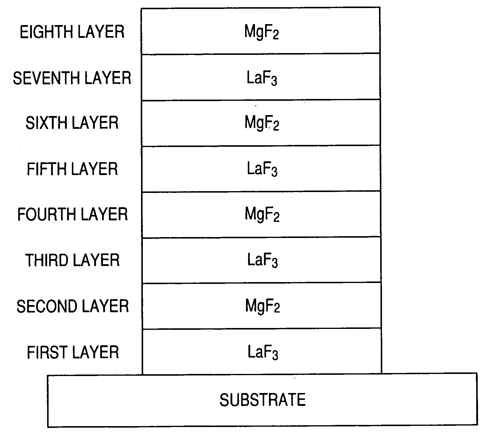
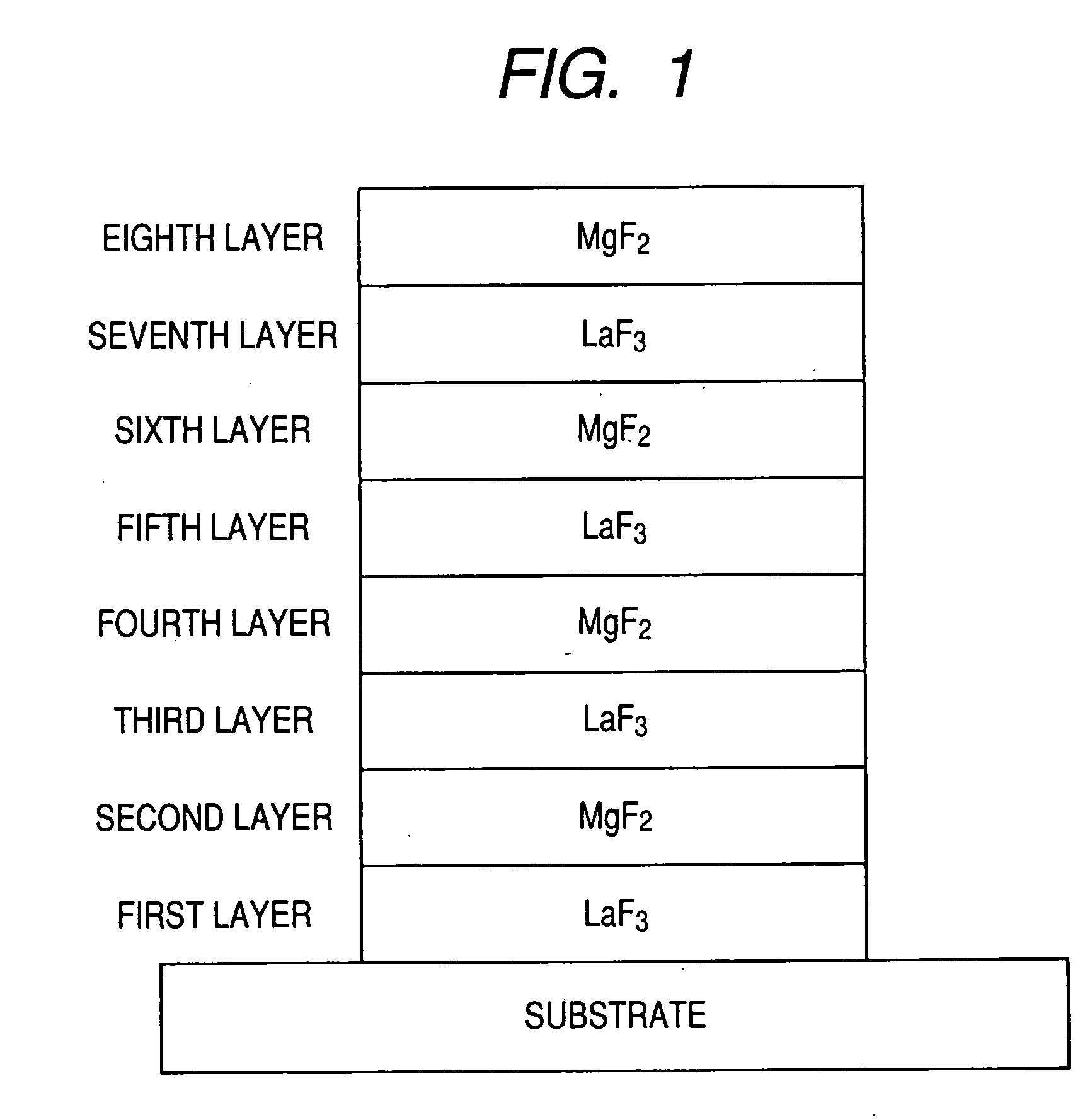
[0029]FIG. 1 is a schematic view showing an anti-reflective film consisting of eight layers for F2 laser (157 nm) in accordance with Example 1 of the present invention. The anti-reflective film of the present example was prepared using an LaF3 film with a refractive index of 1.765 at a wavelength of 157 nm for a high refractive-index layer, and an MgF2 film with a refractive index of 1.466 at a wavelength of 157 nm for a low refractive-index layer. Table 1 shows the optical film thickness of each layer of the anti-reflective film for ultraviolet light with a designed central wavelength of λ0=157 nm. The refractive-index layers were sequentially formed by use of a vacuum evaporation method so as to have the thicknesses shown in Table 1, respectively. In the present example, calcium fluoride was used as a substrate.

TABLE 1Optical FilmMaterialThicknessMedium on lightairincidence sideEighth layerMgF20.2588λ0Seventh layerLaF30.2639λ0Sixth layerMgF20.2614λ0Fifth layerLaF30.1138λ0Fourth ...

example 2

[0035] An anti-reflective film in accordance with the present example has a six-layer structure having high refractive-index layers and low refractive-index layers alternately stacked. The anti-reflective film was prepared using an LaF3 film with a refractive index of 1.765 at a wavelength of 157 nm for a high refractive-index layer, and an MgF2 film with a refractive index of 1.466 at a wavelength of 157 nm for a low refractive-index layer. Table 2 shows the optical film thickness of each layer of the anti-reflective film for ultraviolet light with a designed central wavelength of λ0=157 nm. The refractive-index layers were sequentially formed by use of a vacuum evaporation method so as to have the thicknesses shown in Table 2, respectively. In the present example, calcium fluoride was used as a substrate.

TABLE 2OpticalFilmMaterialThicknessMedium on lightairincidence sideSixth layerMgF20.2534λ0Fifth layerLaF30.2645λ0Fourth layerMgF20.2667λ0Third layerLaF30.1207λ0Second layerMgF20...

example 3

[0038] An anti-reflective film in accordance with the present example has a six-layer structure having high refractive-index layers and low refractive-index layers alternately stacked. The anti-reflective film was prepared using an LaF3 film with a refractive index of 1.765 at a wavelength of 157 nm for a high refractive-index layer, and an MgF2 film with a refractive index of 1.466 at a wavelength of 157 nm for a low refractive-index layer. Table 3 shows the optical film thickness of each layer of the anti-reflective film for ultraviolet light with a designed central wavelength of λ0=157 nm. The refractive-index layers were sequentially formed by use of a vacuum evaporation method so as to have the thicknesses shown in Table 3, respectively. In the present example, calcium fluoride was used as a substrate.

TABLE 3OpticalFilmMaterialThicknessMedium onairlightincidencesideSixth layerMgF20.269λ0Fifth layerLaF30.274λ0Fourth layerMgF20.57λ0 Third layerLaF30.205λ0Second layerMgF20.079λ0...


PUM

PropertyMeasurementUnit
wavelengthaaaaaaaaaa

Abstract

In an anti-reflective film comprising alternating layers of high refractive-index layers and low refractive-index layers, by designing such that a designed central wavelength λ0 is within a wavelength range of 141 nm to 189 nm, and that when the first to eighth layers as counted from a substrate have optical film thicknesses d1 to d8 respectively, the equations of: 0.45λ0≦d1≦0.65λ0; 0.05λ0≦d2≦0.20λ0; 0.29λ0≦d3≦0.49λ0; 0.01λ0≦d4≦0.15λ0; 0.05λ0≦d5≦0.20λ0; 0.23λ0≦d6≦0.28λ0; 0.23λ0≦d7≦0.28λ0; and 0.23λ0≦d8≦0.28λ0 are satisfied, the anti-reflective film can be formed so as to have a low reflectance for a light incident at such a large angle as 30 degrees or more, without increasing the whole thickness of the film.

Description

BACKGROUND OF THE INVENTION [0001] 1. Field of the Invention [0002] The present invention relates to an anti-reflective film coated on a surface of an optical element and an optical element having an anti-reflective film, and particularly to an anti-reflective film effective for ultraviolet light with a wavelength of 140 to 210 nm. [0003] 2. Description of the Related Art [0004] Generally, as an anti-reflective film in an optical element such as an optical lens, a multilayer film is used which has high-refraction films and low-refraction films stacked in layers. The larger the number of the layers, the better the anti-reflective function of the film. However, when the number of layers of an anti-reflective film is increased in order to improve the anti-reflective function, the whole thickness of the anti-reflective film increases. When the thickness of the anti-reflective film becomes large, the transmittance of the anti-reflective film will lower to degrade the function as an optic...

Claims


Application Information

Patent Timeline
Patent Type & Authority Applications(United States)
IPC IPC(8): G02B1/11G02B5/08
CPCG02B1/115
Inventor OTANI, MINORUBIRO, RYUJIFUKUSHIMA, HIROTAKA
Owner CANON KK
Why Eureka
Try Eureka