DC chopper and DC chopping method for doubly fed induction generator system

a generator system and dc hopper technology, applied in the field of methods, can solve the problems of excessively large selection range of rotor-side converters, the influence of increased wind power installed capacity on the electric grid cannot be simply ignored any more, and achieve the effect of flexible control of the converter

Inactive Publication Date: 2013-02-28
DELTA ELECTRONICS (SHANGHAI) CO LTD
View PDF6 Cites 25 Cited by
  • Summary
  • Abstract
  • Description
  • Claims
  • Application Information

AI Technical Summary

Benefits of technology

[0019]By using the DC chopper of the present invention and the method thereof, the input terminal of the control unit is electrically coupled to two terminals of the DC capacitor of the converter, so as to detect a DC voltage in real time. If the detected DC voltage is higher than the predetermined threshold voltage, the control unit outputs a control signal, so as to drive the switch element on, thereby enabling the overvoltage protection module. Simultaneously, the output terminal of the power circuit of the DC chopper can also absorb a part of the rotor inrush current from the DFIG, so that the rotor inrush current flowing into the rotor-side inverter of the converter is low, thereby implementing the over-current protection of the rotor-side inverter. Furthermore, when the DC chopper is driven into operation, the driving signal of the rotor-side inverter does not need to be locked, and thus the control manner of the converter is much more flexible.

Problems solved by technology

However, with continuously increasing of the wind power installed capacity, after grid-connected power generation is implemented, the influence of the increased wind power installed capacity on the electric grid cannot be simply ignored any more.
However, the AC crowbar or DC chopper described above mainly has the following disadvantages: (1) for a passive-mode AC crowbar, over-voltage protection and over-current protection can only be performed after the crowbar is switched in and drive signals from the rotor-side inverter are locked simultaneously, and the switching-in of the passive-mode AC crowbar allows a DFIG to absorb large amounts of reactive power from the electric grid for long term, which is harmful to the stability recovery of the electric power system; (2) during the period in which the grid voltage drops and recovers, an active AC crowbar can deliver reactive power or active power only after the rotor-side inverter is turned on, but the rotor-side inverter and the AC crowbar cannot work at the same, and thus the rotor inrush current and the bus overvoltage may occur again when a converter works again; (3) when being incorporated into the DFIG system, the existing DC chopper can only prevent the bus overvoltage of the converter but cannot prevent the over-current of the rotor-side inverter, thus resulting in an excessively large selection range of the rotor-side converter device; and (4) when the AC crowbar and the DC chopper are used concurrently, if the grid voltage drops, upon being switched to the AC crowbar in the DFIG system, the drive signals of the rotor-side inverter need to be locked, thus causing many inconveniences for flexibly controlling a transducer.

Method used


Image

  • DC chopper and DC chopping method for doubly fed induction generator system
  • DC chopper and DC chopping method for doubly fed induction generator system
  • DC chopper and DC chopping method for doubly fed induction generator system

Examples


Embodiment Construction

[0027]In order to make the technical contents of the present invention more detailed and more comprehensive, various embodiments of the present invention are described below with reference to the accompanying drawings, wherein like reference numerals refer to like elements throughout. However, those of ordinary skills in the art should understand that the embodiments described below are not used for limiting the scope of the present invention. Moreover, the accompanying drawings are only illustrative and are not made according to the original size.

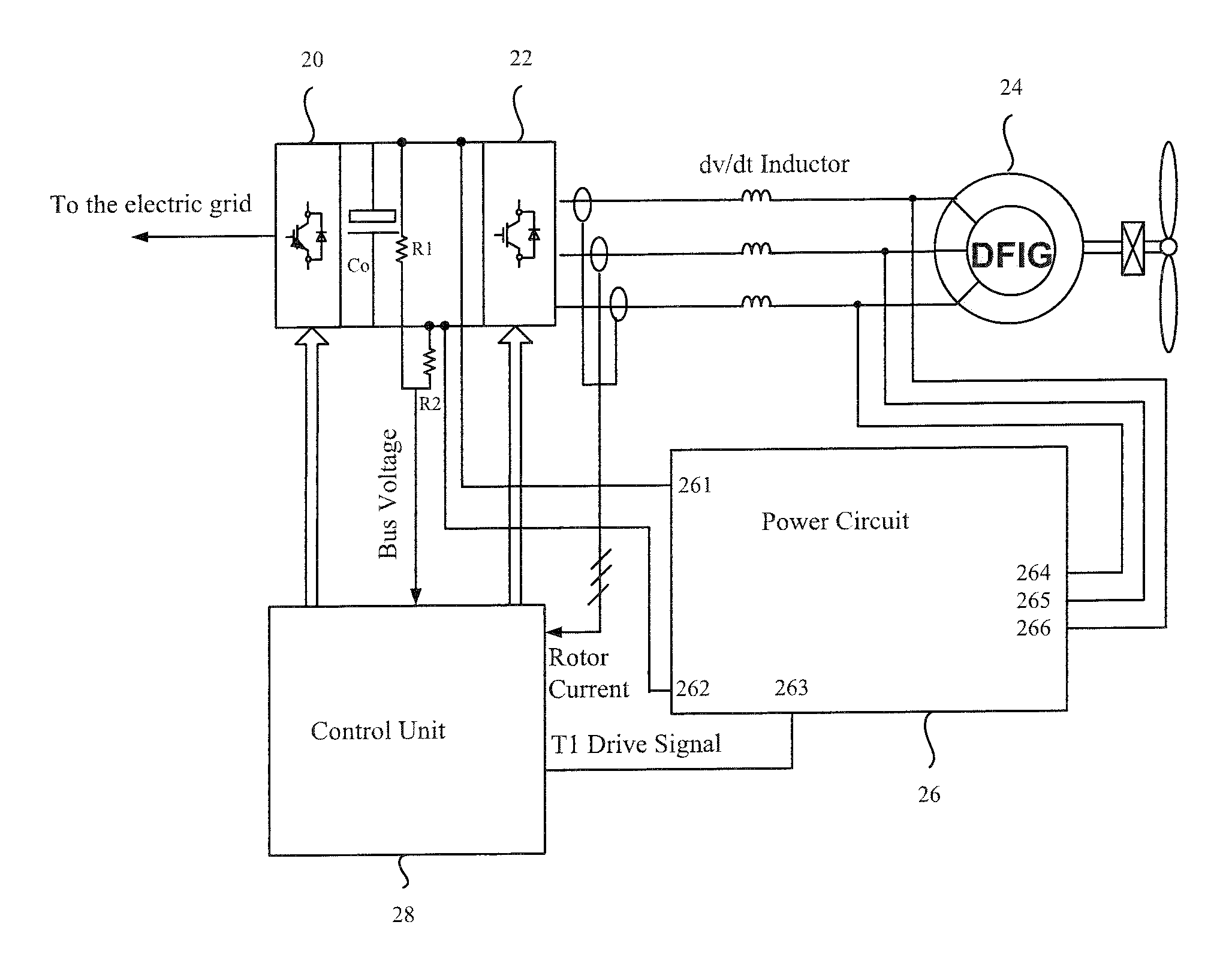
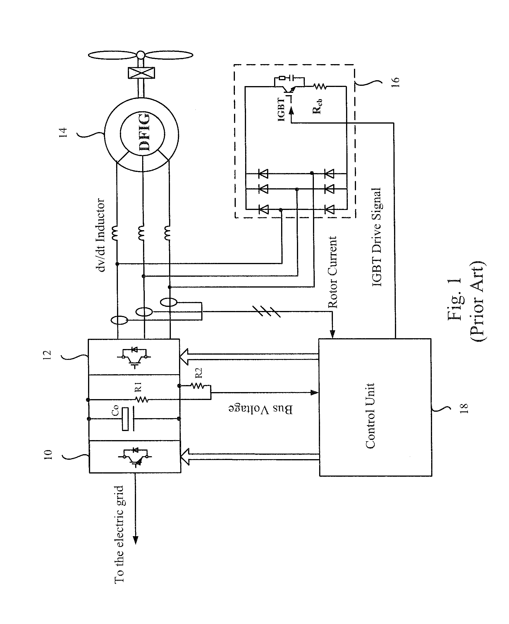
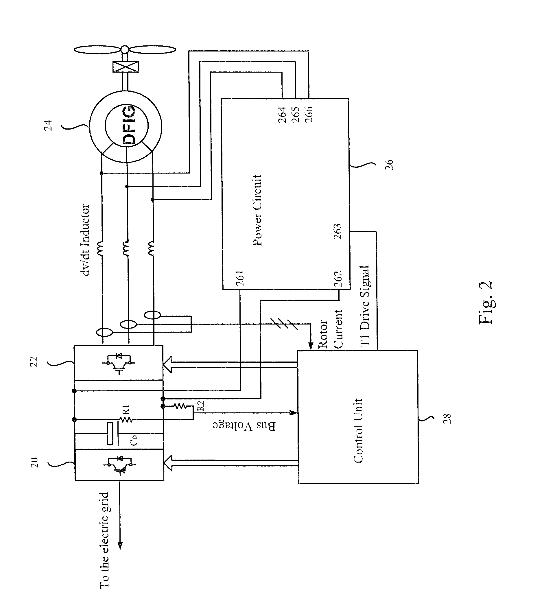
[0028]In each accompanying drawing of the present invention, only the relevant circuits, relevant detected signals, relevant electronic elements or structures used for implementing over-current and / or overvoltage protection of a converter when a DFIG system implements low voltage ride-through are listed. It should be understood by those of skills that if suitable for the present invention, in the DFIG system or other types of wind power ge...


PUM


Abstract

A DC chopper comprising a control unit and a power circuit and a DC chopping method for a DFIG (doubly fed induction generator) system are provided. The input terminal of the control unit is coupled to a DC capacitor of a converter to detect a DC voltage. The power circuit includes input terminals, an overvoltage protection module, a rectifier module and output terminals. The overvoltage protection module comprises at least one discharge unit formed from a discharge resistor and a switch element, and the rectifier module is coupled in parallel to the overvoltage protection module. When a grid voltage drops, the control unit outputs a corresponding control signal to drive the switch element to be ON or OFF, and the output terminal of the power circuit absorbs a portion of rotor inrush current, so as to impose over-current protection.

Description

RELATED APPLICATIONS[0001]This application claims priority to Chinese Application Serial Number 201110243259.5, filed Aug. 23, 2011, which is herein incorporated by reference.BACKGROUND[0002]1. Field of Invention[0003]The present invention relates to a wind power generation technology. More particularly, the present invention relates to a method for low voltage ride-through (LVRT) in a DFIG (doubly fed induction generator) system.[0004]2. Description of Related Art[0005]With the increasingly acute energy crisis and environmental issues, countries all over the world are vigorously developing renewable energy businesses, such as wind power generation and solar energy generation. Taking the wind power generation as an example, the wind power installed capacity in China is developing rapidly, from a stall-regulated wind power system to a variable-speed and constant-frequency (VSCF) wind power system, and from a wind power system with a gear case to a direct-drive wind power system witho...

Claims


Application Information

Patent Timeline
Patent Type & Authority Applications(United States)
IPC IPC(8): H02P9/10
CPCH02P6/00H02M3/02
Inventor WANG, CHANG-YONGZHENG, JIAN-FEILU, FEIYING, JIAN-PING
Owner DELTA ELECTRONICS (SHANGHAI) CO LTD
Why Eureka
Try Eureka