Clock generator with duty cycle control and method

a technology of duty cycle control and clock generator, which is applied in the direction of pulse generator, pulse automatic control, pulse technique, etc., can solve the problems of limiting the use of clock generators in certain high-performance applications, unable to meet the precision and wide dynamic rage required, and difficulty in obtaining a symmetrical duty cycle of 50%

Active Publication Date: 2013-02-28
NAT SEMICON CORP
View PDF6 Cites 18 Cited by
  • Summary
  • Abstract
  • Description
  • Claims
  • Application Information

AI Technical Summary

Problems solved by technology

One problem frequently encountered in oscillator and clock generator design is the difficulty in obtaining a symmetrical duty cycle of 50%, which is clock having equal high and low periods.
As will be seen, many of the solutions may provide acceptable performance in some circumstances but are not able to accommodate the precision and wide dynamic rage required in certain applications such as clock drivers used for switching DC to DC converters used in modern integrated power management systems.
However, shortcomings exist limiting their use in certain high performance applications.

Method used


Image

  • Clock generator with duty cycle control and method
  • Clock generator with duty cycle control and method
  • Clock generator with duty cycle control and method

Examples


Embodiment Construction

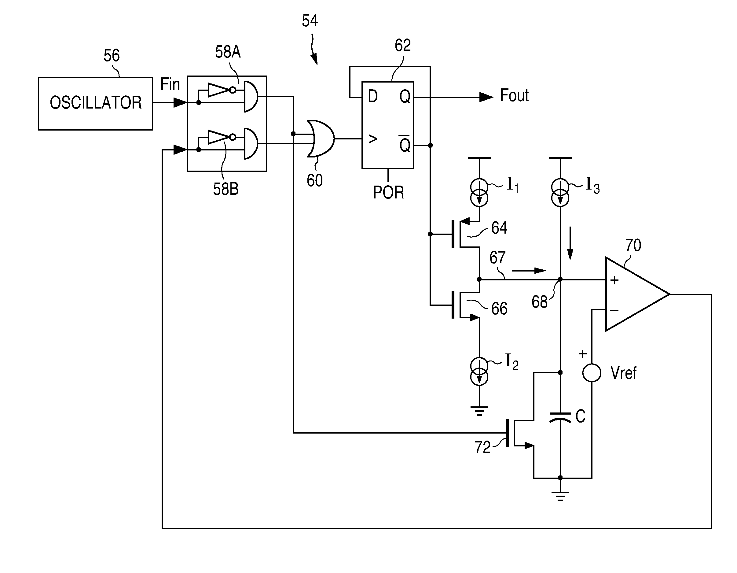
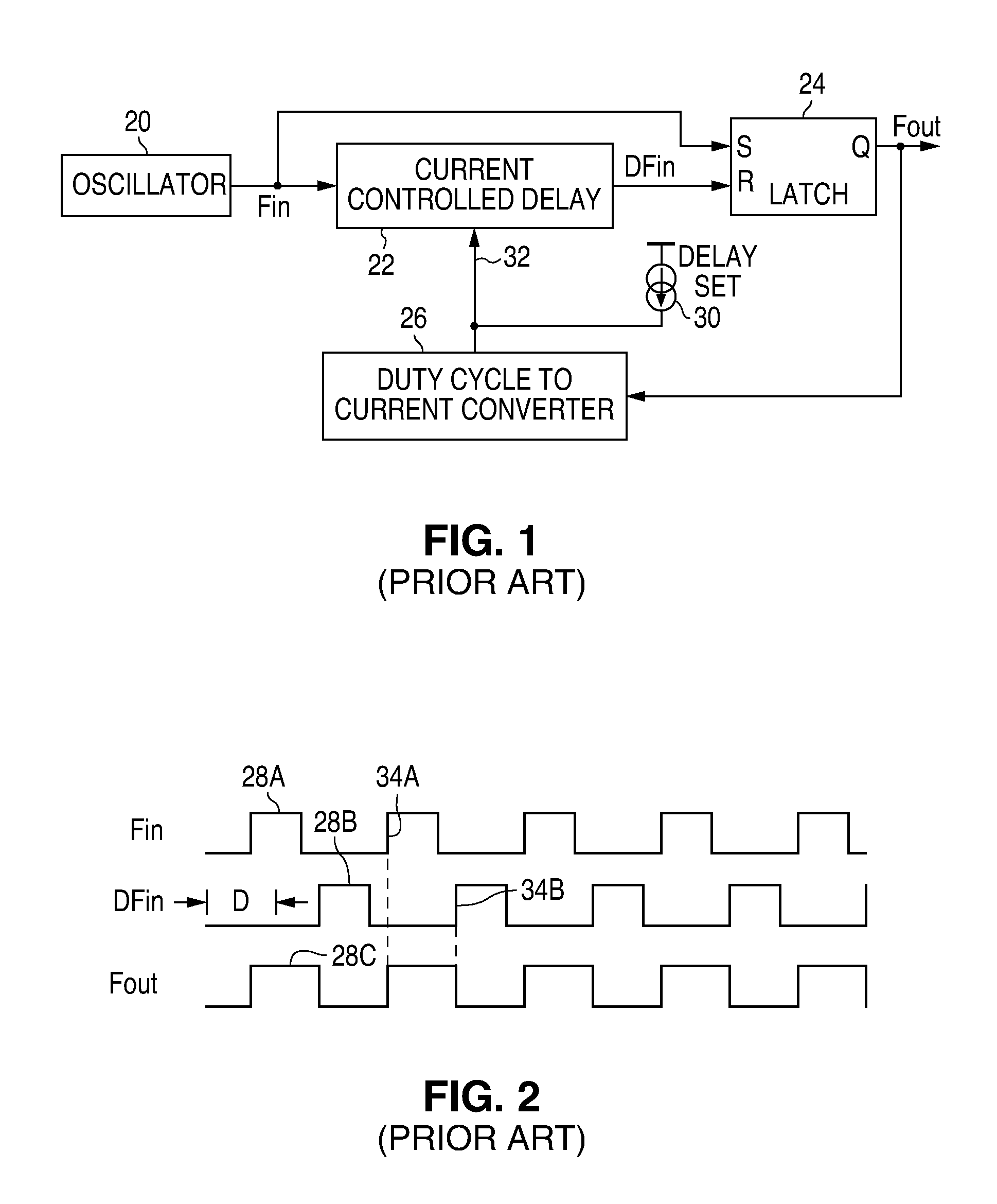
[0018]Referring again to the drawing, the previously described clock generation circuitry of FIG. 1 provides acceptable performance for many applications. However, current clock accuracy requirements require duty cycle control over a ±50% dynamic range for frequencies ranging from 250 KHz to 6 MHz which translates to a delay circuit with an operable span from ±1 μs to ±42 ns. It is not practical or cost effective to provide this kind of performance using the approach of FIG. 1, including the delay circuit 22. In addition, the duty cycle to current converter 26 tends to be sensitive to variations in power supply and the various RC elements used in the circuit.

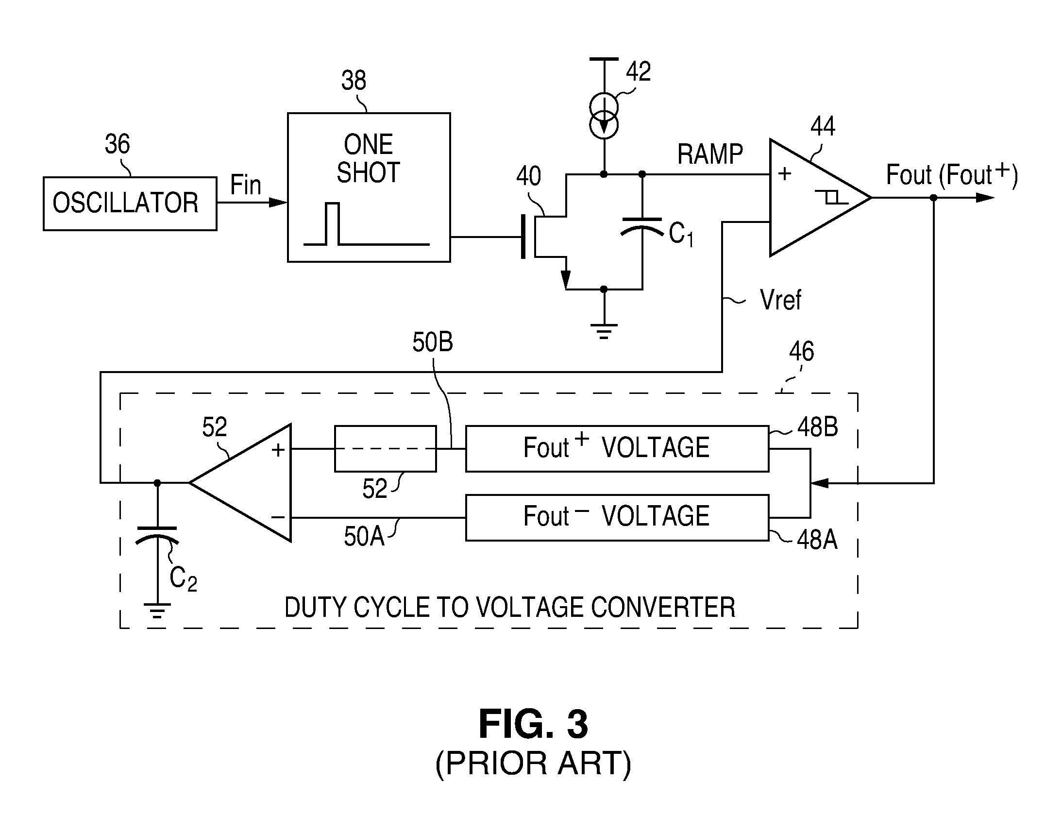
[0019]Similarly, although the previously described clock generator circuit of FIG. 3 provides a relatively wide range of duty cycles, there are shortcomings. Since a comparator 44 is used directly as a pulse shaper, the slow rising edge of voltage Ramp at the input requires that the comparator have a moderate degree of hysteresi...


PUM


Abstract

A clock generator circuit for producing a clock output having a controlled duty cycle is disclosed. A bi-stable circuit provides the clock output which is switchable to a first state in response to an edge of the input clock signal and to a second state in response to a feedback signal. A duty cycle detection circuit is configured to source a current to a node and to sink a current from the node depending upon the output clock state. A capacitor is connected to receive a duty cycle current relating to the current at the node, with a comparator circuit being configured to sense a voltage on the capacitor and to produce the feedback signal when the voltage is at a selected level.

Description

BACKGROUND OF THE INVENTION[0001]1. Field of the Invention[0002]The present invention relates generally to clock generation circuitry and, in particular, the clock generation which includes duty cycle control.[0003]2. Description of Related Art[0004]There are many applications for clock generation circuitry. In some instances, the clock produced by such circuitry must have a very precise duty cycle. The usual definition of duty cycle is the ratio of the clock high period to the total clock period in terms of percentage. One problem frequently encountered in oscillator and clock generator design is the difficulty in obtaining a symmetrical duty cycle of 50%, which is clock having equal high and low periods. This is particularly true when an odd integer divider is involved. Various circuits and methods have been proposed to address these issues. As will be seen, many of the solutions may provide acceptable performance in some circumstances but are not able to accommodate the precision...

Claims


Application Information

Patent Timeline
Patent Type & Authority Applications(United States)
IPC IPC(8): H03L7/097
CPCH03K3/017
Inventor WONG, KERN WAI
Owner NAT SEMICON CORP
Why Eureka
Try Eureka