Antenna device of a mobile terminal

a mobile terminal and antenna device technology, applied in the direction of resonant antennas, antenna earthings, elongated active element feeds, etc., can solve the problems of low antenna efficiency and bandwidth, and the difficulty of avoiding the use of metal components in the design of antenna devices, so as to achieve the effect of not degrading performan

Active Publication Date: 2013-02-28
SAMSUNG ELECTRONICS CO LTD
View PDF9 Cites 42 Cited by
  • Summary
  • Abstract
  • Description
  • Claims
  • Application Information

AI Technical Summary

Benefits of technology

[0010]Aspects of the present invention are to address at least the above-mentioned problems and / or disadvantages and to provide at least the advantages described below. Accordingly, an aspect of the present invention is to provide an antenna device of a mobile terminal, of which performance is not degraded when a metal component is positioned in proximity or when the mobile terminal has a metal case.
[0013]According to exemplary embodiments of the present invention, the metal component that forms the antenna radiator is positioned on the antenna pattern so that a decrease in antenna efficiency and bandwidth due to the metal component can be avoided. In addition, when designing the antenna, the use of the metal component is not restricted.

Problems solved by technology

However, the metal components located near the antenna pattern 110 or the metal case may lower the efficiency and bandwidth of the antenna.
Furthermore, avoiding the use of metal components when designing the antenna device can be difficult.

Method used


Image

  • Antenna device of a mobile terminal
  • Antenna device of a mobile terminal
  • Antenna device of a mobile terminal

Examples


first embodiment

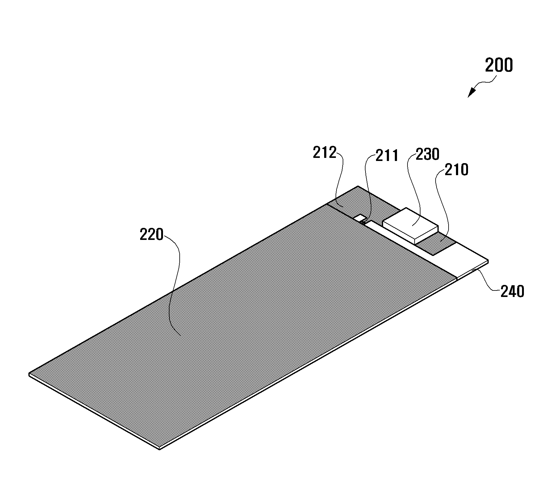
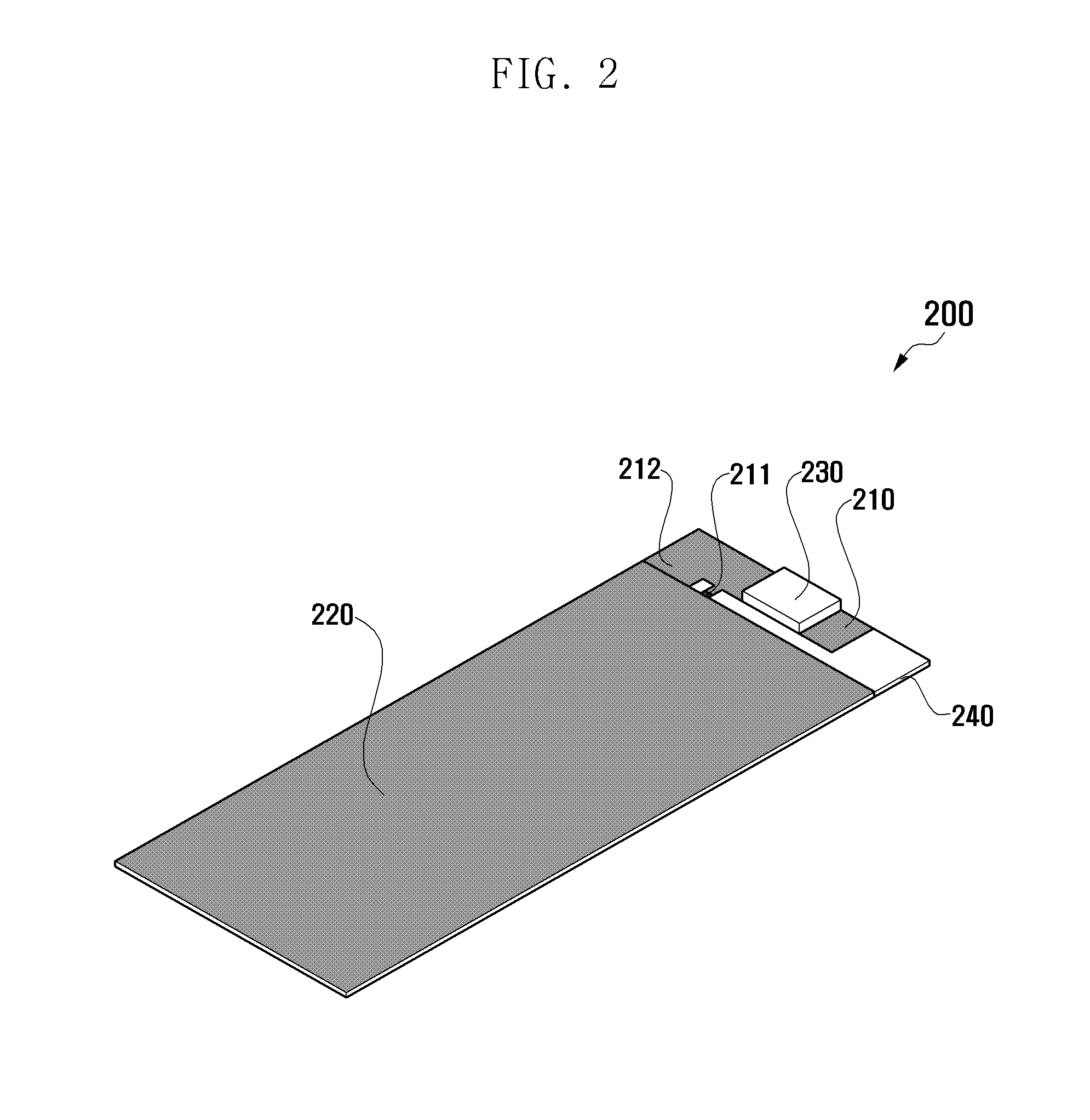
[0042]Referring to FIG. 4, an antenna device 300 of the mobile terminal according to the first modification of the first embodiment is described. Similar to the antenna device 200 of the mobile terminal shown in FIG. 2, the antenna device 300 of the mobile terminal may include a ground line 312 connected to a ground unit 320, which is formed on a PCB 340, and an antenna pattern 310 connected to a feeder 311.

[0043]Compared to the antenna device 200 of the mobile terminal shown in FIG. 2, the antenna device 300 of the mobile terminal may include a speaker 331, an ElectroStatic Discharge (ESD) filter 332, a microphone 334, and a motor 335, each of which is a metal component that is positioned on the antenna pattern 310 to form the antenna radiator. In addition, the antenna device 300 of the mobile terminal may further include an additional antenna pattern 313 connected to the feeder 311. Compared to the antenna device 200 of the mobile terminal shown in FIG. 2, the antenna device 300 o...

second embodiment

[0054]Referring to FIG. 9, an antenna device 600 of the mobile terminal according to the first modification of the present invention is described. Similar to the antenna device 500 of the mobile terminal shown in FIG. 8, the antenna device 600 of the mobile terminal may include an antenna pattern 610 formed of a metal 615 in which a slot 614 is formed, and an IF connector 630, a speaker 631, a PCB 640, a microphone 634 and a motor 635 that are positioned on the antenna pattern 610 to form the antenna radiator.

[0055]In the antenna device 600 of the mobile terminal, the antenna pattern 610 may include parts 610a and 610b that are facing each other with the slot 614 being interposed there between, wherein the parts 610a and 610b are connected to each other through a feeder 611. In addition, compared to the antenna device 500 in FIG. 8, a capacitor 616 is connected to the feeder 611. Accordingly, the antenna device 600 of the mobile terminal can adjust an antenna matching arrangement mo...


PUM


Abstract

An antenna device of a mobile terminal having improved performance by utilizing a metal object located in proximity to the antenna device as an antenna radiator is provided. The antenna device includes an antenna pattern connected to a feeder and a ground line, and a metal component positioned on the antenna pattern and including a metal that forms an antenna radiator.

Description

PRIORITY[0001]This application claims the benefit under 35 U.S.C. §119(a) of a Korean patent application filed on Aug. 22, 2011 in the Korean Intellectual Property Office and assigned Serial No. 10-2011-0083212, the entire disclosure of which is hereby incorporated by reference.BACKGROUND OF THE INVENTION[0002]1. Field of the Invention[0003]The present invention relates to an antenna device of a mobile terminal. More particularly, the present invention relates to an antenna device of a mobile terminal having improved performance by utilizing a metal object located in proximity to the antenna device as an antenna radiator.[0004]2. Description of the Related Art[0005]A mobile terminal has many metal components, located in the limited internal space, to provide various features. Because an antenna is also located within the mobile terminal, the plurality of metal objects are located in proximity of the antenna device. The metal objects can influence the performance of the antenna devic...

Claims


Application Information

Patent Timeline
Patent Type & Authority Applications(United States)
IPC IPC(8): H01Q19/00H01Q5/364
CPCH01Q1/22H01Q1/243H01Q5/364H01Q9/42H01Q5/0055H01Q1/44H01Q1/46H01Q1/48H01Q19/005
Inventor VIN, YOUNG BOOLEE, DONG HYUNHWANG, SOON HOKIM, HAE YEONCHO, BUM JINPARK, SE HYUNBYUN, JOON HO
Owner SAMSUNG ELECTRONICS CO LTD
Why Eureka
Try Eureka